
Frequency/Voltage Converter

The TSC9402 integrated circuit serves dual purposes in electronic applications, functioning as both a voltage-to-frequency and frequency-to-voltage converter. This dual functionality enhances its utility in various measurement scenarios, particularly in conjunction with multimeters. The simplicity of the design allows for easy integration into existing systems, requiring minimal additional components, which streamlines the implementation process.
To utilize the TSC9402 effectively, a single calibration point is established to define the center of the measuring range, optimizing the device for the most commonly measured frequencies. This feature is particularly advantageous in applications where specific frequency ranges are of primary interest, as it allows for quick adjustments and accurate readings.
The output voltage at pin 12, designated as the amplifier output, is influenced by frequency variations. The presence of interference pulses, which can reach levels of 0.7 V, necessitates careful design considerations to ensure accurate measurements. If these interference pulses are detrimental to the multimeter's accuracy, the implementation of a simple resistor-capacitor (RC) network can provide an effective means of suppression, enhancing the reliability of the measurement.
The calculation of the output voltage, U0, through the provided formula underscores the importance of understanding the internal capacitance of the circuit. Since this value can often exceed the nominal 12 pF, users should be aware that the formula may yield relative rather than absolute output values. This characteristic emphasizes the need for careful calibration and possibly adjustment based on the specific application and components used.
Operating over a frequency range from DC to 10 kHz, the TSC9402 is particularly well-suited for applications requiring low-frequency measurements. The calculated output voltage of 3.4 V at 10 kHz illustrates the circuit's ability to provide significant voltage levels under specified conditions. Additionally, the low current draw of 1 mA ensures that the circuit can be integrated into low-power applications without compromising overall system efficiency. This combination of features makes the TSC9402 an excellent choice for a wide range of electronic measurement applications. Teledyne Semiconductor"s Type TSC9402 is a versatile IC. Not only can it convert voltage into frequency, but al so frequency into voltage. It is thus eminently suitable for use in an add-on unit for measuring frequencies with a multimeter. Only a few additional components are required for this.. Just one calibration point sets the center of the measuring range (or of that part of the range that is used most frequently). The frequency-proportional direct voltage at the output (pin 12—amp out) contains interference pulses at levels up to 0.7 V.
If these have an adverse effect on the multimeter, they can be suppressed with the aid of a simple RC network. The output voltage, U0, is calculated by: tfo=C/rei(Ci + 12 pF) R2fm Because the internal capacitance often has a greater value than the 12 pF taken here, the formula does not yield an absolute value.
The circuit has a frequency range of dc to 10 kHz. At 10 kHz, the formula gives a value of 3.4 V. The circuit draws a current of not more than 1 mA.
Related Circuits
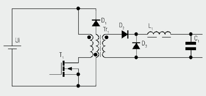
The diagram illustrates the basic construction of a forward converter. In contrast to the flyback converter, which temporarily stores energy before transferring it to the secondary side, the forward converter facilitates direct energy transfer between the primary and secondary...
This circuit is a 12V to 5V converter utilizing a 7805 regulated IC. In a previous article, a circuit for a 12V to 9V converter using the 7809 IC was discussed. The circuit presented here is also a step-down...
The VFC62 is a voltage-to-frequency and frequency-to-voltage converter that effectively transforms analog signals into digital signals. The digital output is presented in an open collector format, where the digital pulse repetition rate is directly proportional to the amplitude of...
A step-up converter followed by an LDO regulator provides improved battery life compared to a traditional SEPIC design when powered by a single lithium-ion cell. The circuit design features a step-up (boost) converter that elevates the input voltage from a...
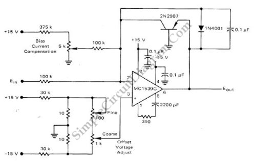
This low-cost logarithmic converter is constructed using an operational amplifier (op-amp) and a transistor. The circuit utilizes a Motorola MC1539G op-amp connected to a PNP transistor. The logarithmic converter circuit is designed to convert linear input signals into logarithmic output...
This is a circuit for a Voltage-to-Pulse Duration Converter. The circuit is designed to convert voltage into pulse duration by integrating a timer IC and an operational amplifier (OP Amp). The Voltage-to-Pulse Duration Converter circuit utilizes a timer IC, typically...