
Emergency Siren circuit Simulates Police

The described circuit utilizes a dual transistor configuration to create a flashing light effect, commonly employed in visual signaling applications. The first transistor acts as an oscillator, while the second transistor functions as a driver for the load, typically an LED or similar light-emitting device. The frequency modulation is introduced through the application of voltage to the base of the first transistor, which alters its conduction state, thereby controlling the oscillation frequency.
When the pushbutton is activated, the circuit initiates a rapid charge and discharge cycle in the 22 µF capacitor. The charging phase causes the voltage across the capacitor to rise, which in turn increases the base current of the first transistor. This results in a higher frequency of oscillation, producing a brighter flash from the load. Upon releasing the button, the capacitor begins to discharge, leading to a decrease in base current and a corresponding drop in oscillation frequency. The rate at which the frequency changes is influenced by both the capacitance value and the resistance of the 100 kΩ resistor, which forms an RC time constant.
If the pushbutton remains unpressed, the oscillation will eventually halt, and the circuit will enter a low-power state. This feature is particularly advantageous as it conserves energy and eliminates the necessity for a dedicated power switch, allowing for a more compact and efficient design. The simplicity of the circuit, combined with its effective modulation capabilities, makes it suitable for a variety of applications, including decorative lighting, alert systems, and educational projects.The heart of the circuit is the two transistor flasher with frequency modulation applied to the base of the first transistor. When the pushbutton is depressed, the frequency of oscillation climbs to a peak and when the button is released, the frequency descends due to the rising and falling voltage on the 22 uF capacitor.
The rate of change is det ermined by the capacitor value and the 100k resistor from the pushbutton. The oscillation eventually stops if the button is not depressed and the current consumption drops to a tiny level so no power switch is needed. 🔗 External reference
Related Circuits
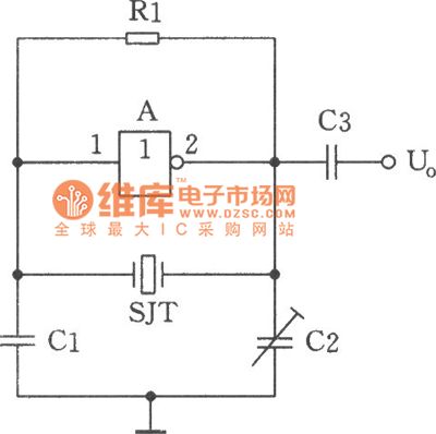
The image depicts a sine wave oscillator that consists of a quartz crystal (SJT) and gate A of the hex inverter IC CD4069. Compared to a standard RC phase-shift oscillator, the frequency stability of a crystal oscillator can achieve...
This document provides a guide on understanding a simple computer system and its operation. It will examine the BASIC programming language and its statements, enabling communication with external circuitry. The document will also explore how to interface electronic circuits...

This operational amplifier circuit utilizes resistor and transistor feedback elements to function as a nonlinear amplifier. The resistors R4 and R6 can be adjusted to modify the breakpoints as needed. This operational amplifier circuit is designed to operate within the...
This is a classic frequency divider by two, implemented using a T-flip flop circuit, specifically with IC1 [4011]. In this circuit, the frequency from the network, after limiting the negative half-period of the sine wave and transforming it into...
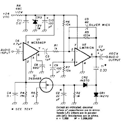
An audio signal applied to VI is passed through the operational amplifier 741, U2. After being amplified, the output signal V2 is sampled and applied to a negative voltage doubler/rectifier circuit composed of diodes CR1 and CR2, along with...
There is a modification to the RC delay circuits that some may want to consider. If a shorter discharge time is desired, this modification enables the circuit to restart more quickly. The modification to the RC delay circuit involves adjusting...