
Energy Saving Night Light circuit

The circuit described involves the use of fluorescent lamps functioning as a ballast or electronic ballast inverter. This design utilizes capacitors to reduce voltage reactance, which is critical in managing the electrical characteristics of the circuit. The ignition process for the auxiliary electrodes is facilitated by the inclusion of resistors with a resistance of approximately 150 Ohms. The operational procedure indicates that only one resistor is necessary to initiate the lamp, although this may result in longer blinking periods before stable operation is achieved. Notably, the design omits the use of a filament, which is typically employed in traditional fluorescent lamps, and instead, the filament connections are short-circuited.
The circuit is designed for relatively low-voltage fluorescent tubes, making it suitable for operation with battery power. This is advantageous for portable applications where power supply constraints exist. The drive circuit must be capable of handling a considerable supply voltage to ensure the fluorescent lamps function effectively.
In the context of the capacitors used within this circuit, two examples are provided: one capacitor has a capacitance of 430 nF rated for 200 V, while the other has a capacitance of 470 nF rated for 250 V. It is essential that the capacitors are rated for at least AC 250 V or DC 400 V to ensure reliable operation and longevity. The durability of capacitors in this application is a critical consideration, as aged or degraded capacitors can lead to failure, potentially resulting in short circuits and subsequent damage to the entire system. Regular monitoring and replacement of these components may be necessary to maintain circuit integrity and performance. The lamps are usually used as ballast or electronic ballast inverter. Here it is used to reduce voltage capacitor reactance. Interesting is also the method of ignition of the auxiliary electrodes involved over 150 Ohm resistors. To start simply involve only one, but the lamp is switched on for longer blinks. Filament is not used and are short-circuited. The operation is relatively low-voltage fluorescent tubes, it looks like it worked pretty well and easy to drive on battery power.
The drive would only have to load a relatively large supply voltage, or fluorescent lights. In a fluorescent lamp had capacity of 430 nF capacitor and the voltage was only 200 V. The second had a capacity of 470 nF and a voltage of 250 V. In any case, the capacitor should be at AC 250 V or 400 V DC at least I wonder how long used Capacitors can withstand before it breaks or shorted out and burns down the entire system? 🔗 External reference
Related Circuits
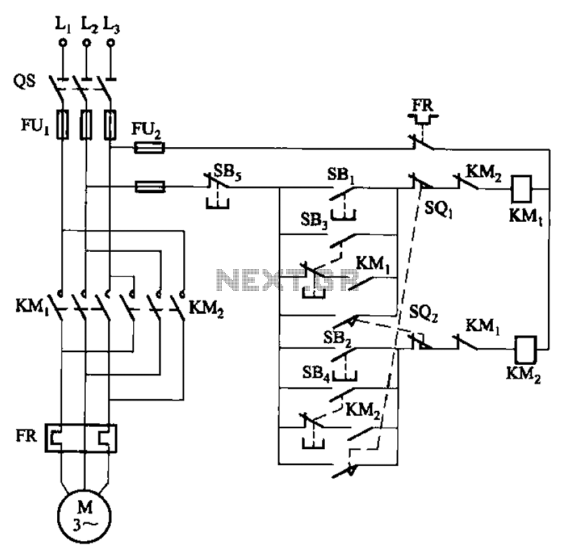
The circuit depicted in Figure 3-27 features a jog function that allows for precise adjustments of moving components. In the figure, SB3 and SB4 represent the forward jog and reverse jog buttons, respectively. When the SB3 button is pressed,...
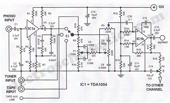
This simple stereo encoder circuit schematic is built with two ICs, MMC4066E and MMC4047, along with one transistor, BC547B. The audio output is taken from pins 2 and 3 of IC1. The stereo encoder circuit utilizes the MMC4066E, which is...

This circuit generates a wide variety of noise types, including white noise, pink noise, high pass noise, grainy noise (with adjustable graininess), and adjustable random gates. It is designed for enthusiasts of noise generation. The noise source is derived...
A CD4017 is configured as a senary counter, with an input clock frequency of 300 Hz. Diodes VD1 to VD9 and resistors R1 to R3 form three three-input OR gates, which can each receive two 50 Hz three-phase wave...
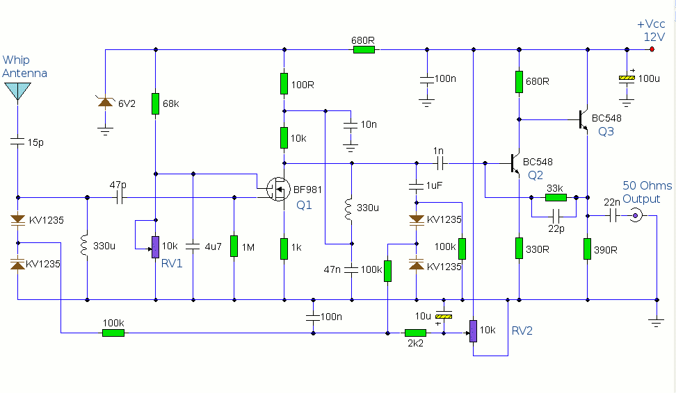
The antenna amplifier circuit comprises approximately 40 components, featuring two NPN transistors (BC548), one MOSFET (BF981), two varicap diodes (KV1235), and a 6.2V zener diode. It includes a 330µH inductor/coil, which can be modified for operation on different frequency...
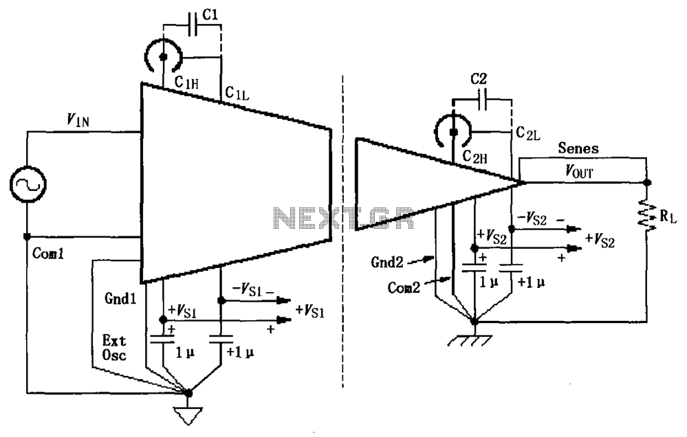
The basic connection circuit for ISO120/121 includes signals and power supply. Each power supply terminal must have a 1 µF tantalum capacitor as a bypass filter, and the printed circuit board layout should allow for the bypass capacitor to...