
Stereo Encoder Circuit

The stereo encoder circuit utilizes the MMC4066E, which is a quad bilateral switch, to manage the audio signals effectively. This IC is responsible for switching the audio channels, allowing for the separation of left and right audio signals, essential for stereo sound. The MMC4047, on the other hand, functions as a timing and frequency generation IC, which can facilitate the modulation of the audio signals for encoding purposes.
The BC547B transistor serves as a buffer or amplifier in the circuit, ensuring that the output signals maintain their integrity and strength when transmitted to the subsequent stages or to the output device. The configuration of these components allows for a compact and efficient stereo encoding solution suitable for various audio applications.
In a typical setup, the audio inputs are fed into the MMC4066E, where they are processed and switched according to the control signals provided by the MMC4047. The output from the MMC4066E is then amplified by the BC547B, ensuring that the final stereo output is clear and powerful enough for driving speakers or other audio devices. Proper power supply decoupling and grounding techniques should be employed to minimize noise and ensure stable operation of the circuit.This simple stereo encoder circuit schematic is build with 2 IC MMC4066E and MMC4047 and one transistor BC547B. On IC1 2 and 3 pins is the audio output whi.. 🔗 External reference
Related Circuits
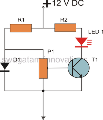
All semiconductors exhibit the tendency to alter their fundamental characteristics in response to changes in ambient temperature. Basic electronic components such as transistors and diodes are particularly susceptible to variations in case temperature. The alteration in their characteristics is...
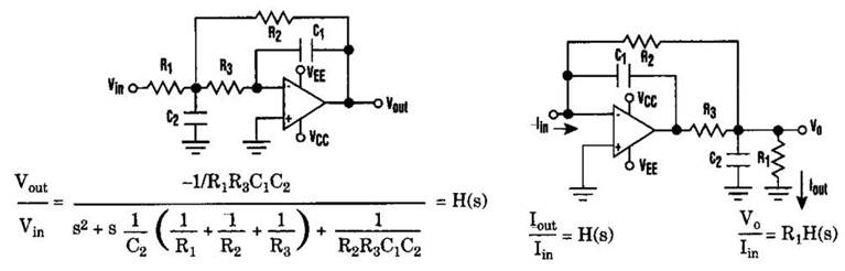
Current-Driven Sallen-Key Filter Circuit Diagram. The low-pass Sallen-Key filter is a staple for designers because it contains few components (A). The Sallen-Key filter is a widely used active filter topology that employs operational amplifiers (op-amps) to achieve desired filtering...
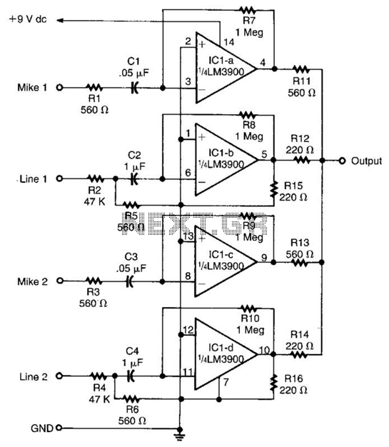
Designed around an LM3900 quad op amp, this mixer combines two line inputs and two microphone inputs, summing them at the output terminal. Resistors R7 through R10 can be adjusted to vary the gain, approximately +23 dB. The mixer circuit...
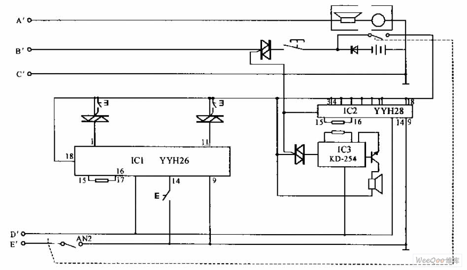
The internal telephone circuit is depicted below. By making minor enhancements to a toy telephone, it can be transformed into a functional internal telephone. This device comprises several components, including the phone unit, a decoding circuit, a ringing circuit,...
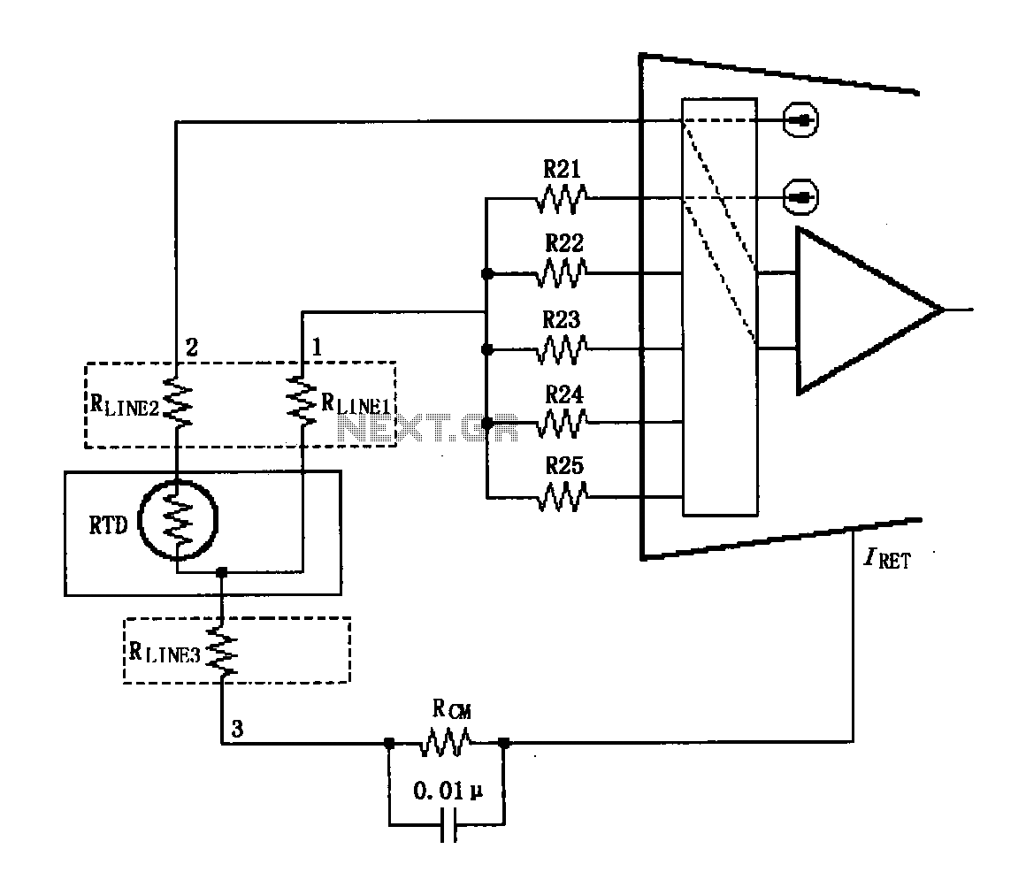
The circuit diagram illustrates the three-wire RTD connection for the XTR108. It is important to note that the lead resistance of the RTD sensor can introduce measurement errors. In the provided figure, connections "1" and "2" represent the lead...
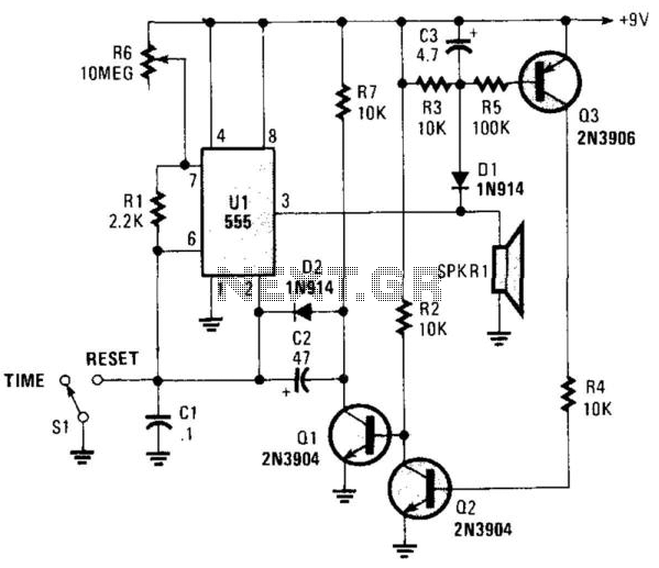
This circuit operates in astable mode and produces a tone at the end of the first period, which can last several minutes. When switch SI is in the time position, transistor Q3 is turned off because pin 3 of...