
enhanced 4 digit alarm

The circuit operates on a simple principle of keypress detection and relay control, providing a straightforward yet effective means of securing access. The keypad's layout is crucial; it should be a matrix type with a common terminal to ensure proper functionality. Each keypress is registered through a momentary switch mechanism, where pressing the key connected to terminal "E" sends a signal to activate the relay, which can then control external devices such as alarms or locks.
The relay's operation is indicated by the green LED, which serves as a visual cue for the user, confirming that the system is armed when illuminated. The design allows for flexibility in code length, accommodating both four-digit and five-digit configurations, thus enhancing security based on user requirements.
The code entry logic is implemented to ensure that any incorrect keypress resets the sequence, providing an additional layer of security against unauthorized access attempts. This feature is particularly useful in preventing brute-force attacks, as the system does not allow for partial code entry to be completed if any wrong key is pressed.
The circuit's versatility extends beyond burglar alarm systems; it can be adapted for various applications requiring secure access control, such as electronic locks or automated systems. The support material provided aids in the construction and troubleshooting of the circuit, ensuring that users can implement the design effectively and securely.
For those looking to create a more complex system, the option to expand the keypad to 16 keys allows for a greater number of unique codes, further enhancing the overall security of the application. The inclusion of detailed construction guides and parts lists facilitates the assembly process, making this circuit accessible to both novice and experienced electronics enthusiasts.Circuit Pressing a single key on the keypad - will energize the relay. Entering a four-digit code of your choice - will de-energize the relay. The circuit was designed to control the Modular Burglar Alarm System - but it will have other applications. If you require added security - A Five-Digit Version - of the circuit is also available. The Keypa d must be the kind with one common terminal - and a separate connection for each key. On a 12-key pad - look for 13 terminals. The matrix type with 7 or 8 terminals will NOT do. On the Support Page you`ll find details of how to Make Your Own Keypad. The relay is energized by pressing a single key. Choose the key you want to use - and connect it to terminal "E". Choose the four keys you want to use for your security code - and connect them to "A B C & D". Wire the common lead to R1- and all the remaining keys to "F". When you press "E" the relay energizes - and the 12-volt output moves from the "off" to the "set" terminal. The green LED also lights. It provides a visual indication that the alarm is set. When you press keys "A B C & D" in the right order - the relay de-energizes - and the 12-volt output returns to the "off" terminal.
The green LED is also extinguished - to indicate that the alarm is switched off. The remaining keys - those not wired to "A B C D & E" - are connected to "F". Whenever one of these "Wrong" keys is pressed - the attempted code entry fails - and the code entry sequence is reset. The same thing happens if "C" or "D" is pressed out of sequence. If "C" is pressed before "B" - or "D" is pressed before "C" - the attempted code entry will fail. And the code entry sequence will reset. With a 12-key pad - over 10 000 different codes are available. If you need a more secure code - you could simply use a bigger keypad with more "Wrong" keys wired to "F".
A 16-key pad gives over 40 000 different codes. If you make a mistake while entering the code - simply start again. The Support Material for this circuit includes a step-by-step guide to the construction of the circuit board - a parts list - a detailed circuit description - and more. 🔗 External reference
Related Circuits

This post discusses the interfacing and operation of Analog-to-Digital Converters (ADCs). An ADC is a device that converts the analog signals from transducers into digital signals, enabling computers to process the data. ADCs are essential for obtaining meaningful results...

This water level alarm circuit can be utilized as a water level indicator to monitor the desired water level in various applications, such as tanks, swimming pools, or any location where water is stored. The circuit is constructed using...
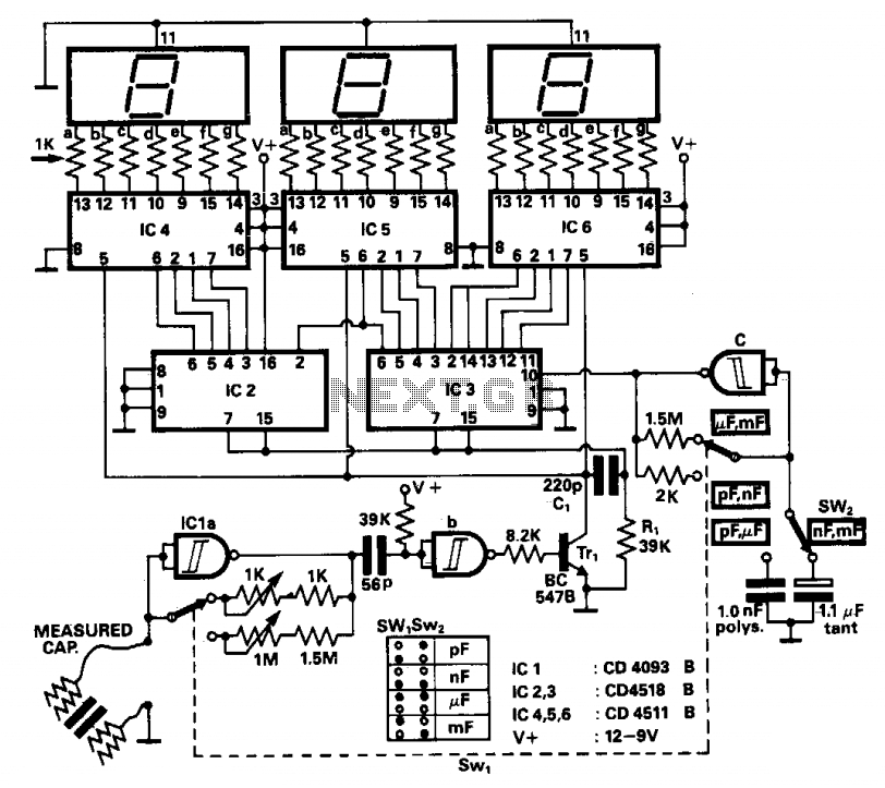
The operation principle involves counting the number of pulses generated by a constant frequency oscillator over a fixed time interval, which is produced by another lower frequency oscillator. This lower frequency oscillator utilizes the capacitor being measured as the...

This is a simple proximity switch utilizing the IC 4049. The IC 4049 is a bipolar monolithic integrated circuit designed for metal detection systems and proximity sensing applications. It includes an oscillator formed by an external parallel resonant tank...

The circuit consists of an ultrasonic transmitter and a receiver that operate at the same frequency. Ultrasonic piezoelectric transducers serve as the output and input devices, respectively, with their frequency of operation determined by the specific devices used. The...
The simplest Analog to Digital Converter (ADC) can be constructed as shown in Figure 1. The input voltage, which can range from zero up to the power supply voltage (Vcc), is converted to a parallel binary code at the...