
Simple Proximity Detector & Alarm Circuit

The proximity switch circuit based on the IC 4049 operates by utilizing the characteristics of an oscillator integrated with a resonant tank circuit. The tank circuit consists of an inductor (coil) and capacitors (C1 and C2), which are tuned to resonate at a specific frequency. The IC 4049's oscillator generates an alternating current (AC) signal that is influenced by the presence of nearby metallic objects.
When a metal object approaches the coil, it alters the electromagnetic field around the coil, thereby affecting the resonant frequency of the tank circuit. This interaction leads to a reduction in the voltage amplitude across the tank circuit. The oscillator's output is monitored through the feedback resistor connected to pins 2 and 5. As the voltage amplitude diminishes, the circuit's feedback mechanism responds by increasing the resistance. This adjustment effectively increases the detection range of the circuit.
The circuit can achieve a maximum detection range of approximately 1 inch when a high Q coil is employed, which is essential for maintaining sensitivity and accuracy in metal detection applications. To optimize the circuit for different detection distances, the values of the capacitors C1 and C2 can be adjusted. This tuning allows the user to set the circuit for specific operational distances, ensuring reliable detection of metal objects.
In summary, the IC 4049-based proximity switch circuit is a versatile solution for metal detection and proximity sensing, leveraging an oscillator and resonant tank circuit to provide adjustable and reliable performance. The careful selection of components and tuning of the circuit parameters are critical for achieving the desired detection range and sensitivity.This is a simple proximity switches with IC 4049th The IC4049 is a bipolar monolithic integrated circuit for use in metal-detection system / proximity sensing applications IC4049 includes an oscillator constituted by an external parallel resonant tank circuit and a feedback resistor connected 2-5 The internal oscillator operates near the resonant frequency of the tank is brought circuit. As a metal object near the coil begins to decrease the amplitude of the voltage across the tank gradually. If the envelope of the oscillation a certain level, the greater the resistance the greater the travel distance.
Detection-point range with a high Q coil. Maximum possible range can be achieved with a well extended to 1-inch drive circuit. Only So this circuit, the tuning circuit to a certain range. For making it easy to a metal coil at the desired distance (1 inch) square and adjust the resistance, C1 and C2 (make Pin2 or 5) one of the outputs in the state change. 🔗 External reference
Related Circuits

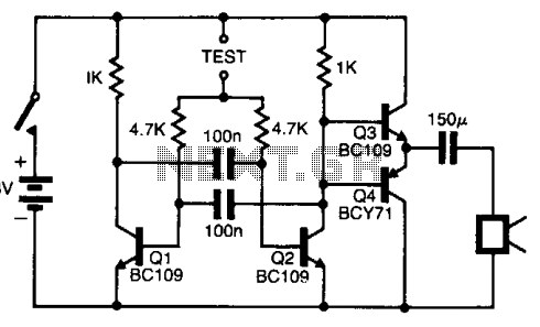
This is a rather sensitive circuit which will detect minute variations of a magnetic field, particularly the Earth magnetic field. The principle is based on an audio beat tone generated by two identical oscillators. These must be built in...
The pitch of the tone is dependent upon the resistance under test. The tester will respond to resistance of hundreds of kilohms, yet it is possible to distinguish differences of just a few tens of ohms in low-resistance circuits....
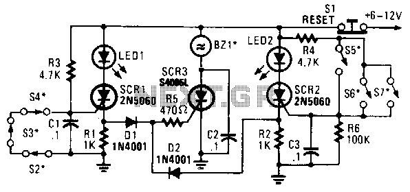
In this circuit, a low-powered silicon-controlled rectifier (SCR) is utilized to trigger a higher-powered SCR. When a switch is opened (S2, S3, S4) or closed (S5, S6, S7), either SCR1 or SCR2 is activated. This action subsequently triggers SCR3...

A 220V AC input is converted to a DC operating voltage of approximately 3.3V using a capacitive G buck regulator, a rectifier diode (VD), and a filter capacitor connected to an NE555 integrated circuit (IC). The IC functions as...

An electric power limiter circuit restricts the user load, ensuring that household appliances operate within a specified normal current range. When the load exceeds a predetermined threshold, the power supply is disconnected. This circuit utilizes the high-power integrated TWH8778...
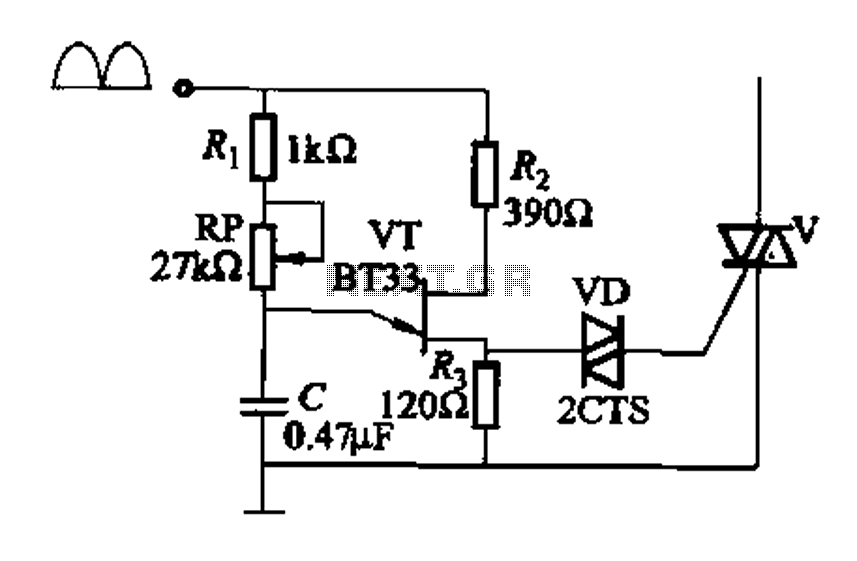
Figure 16-29 (a) illustrates the trigger output through a resistor R2, while Figure 16-29 (b) depicts the integration of a programmable unidirectional transistor (PUT) trigger circuit. The adjustable potentiometer RP can modify the conduction angle of the TRIAC to...