
EPROM adapter for ATMEL 89 Series Flash Microcontroller Programmer

The circuit involves a diode (D1) and a resistor (R1) that serve to isolate the VDD supply during the programming process of 24-pin devices. The diode is oriented in such a way that it allows current to flow from the power supply to the device while preventing any backflow that could potentially disrupt the programming process. The resistor is used to limit the current to safe levels, ensuring that the connected devices are not subjected to excessive voltage or current that could lead to damage.
The configuration of jumper J3 is critical for the operation of this circuit. When programming a 24-pin device, J3 must be shorted, which connects the programming circuitry in a manner that is appropriate for the 24-pin configuration. Conversely, for 28-pin devices, J3 must be left open, altering the circuit path to accommodate the different pin arrangement. This flexibility allows the programmer to be used with multiple device types while ensuring that the correct operational parameters are maintained.
The compatibility of EEPROMs with their EPROM counterparts is an important feature of this circuit, allowing for seamless integration and programming without the need for extensive modifications. This pin compatibility simplifies the process of updating or replacing devices in existing designs.
It is essential to approach the use of this circuit with caution. Working with electrical devices, especially those involving high voltages, can pose significant risks. The provided diagrams and instructions should be followed meticulously, as any deviation could lead to device failure or personal injury. Users are encouraged to reach out for clarification or assistance as needed, utilizing the provided contact resources.Diode D1 and resistor R1 provide the VDD isolation when programming the 24 pin devices. The jumper J3 must be shorted for 24 pin devices, and open circuit for 28 pin device programming. Following EEPROMs are pin compatible with their EPROMs version, We are not responsible for any injuries or damage caused by information from this website! Working with electricity is dangerous for your life, especially diagrams related to high voltage! We do not guarantee success in building devices using our diagrams! They are not tested by us. For questions about diagrams use author info below diagram or our contact page. Thank you! 🔗 External reference
Related Circuits
This is a very simple project using a printed circuit board and 8 components. It will flash an ordinary 3mm or 5mm (1/8" or 1/4") LED at a rate of about one flash per second. This circuit works on...

There have described the involvement benefited LM3909 circuit, which is quite expensive. That's why I prefer to use a much cheaper known timer 555th. Involvement of the tree is a very simple scheme is to figure 2. It is...

This is a design for a flashlight that two 220 V alternating lights can control. The flashlight uses only one IC. IC1a IC1c to be used for the flashing signal generation. The output of IC1c thyristor T1 is controlled,...

This circuit is designed as a warning flasher to alert road users to dangerous situations in low-light conditions. It can also function as a bicycle light, adhering to traffic regulations. White LEDs are recommended for use as a front...
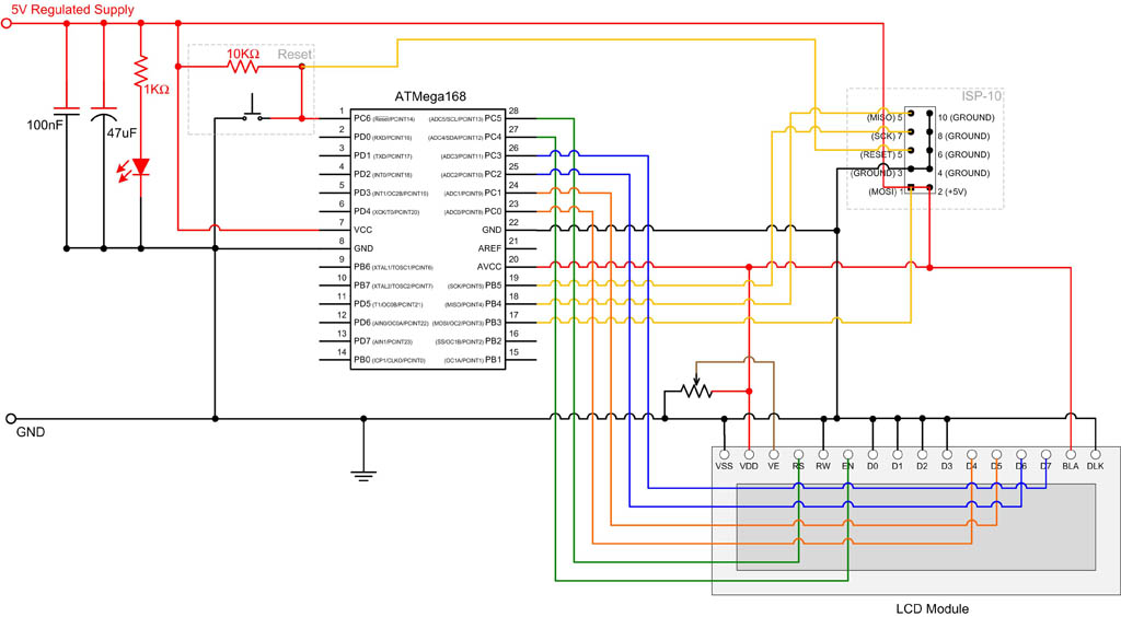
EEPROM (Electrically Erasable Programmable Read-Only Memory) is non-volatile memory, meaning it retains data even after power is removed. The ATmega168 microcontroller includes 512 bytes of EEPROM, which can be utilized to store system parameters and small amounts of data....
For the following circuit of the JDM PIC microcontroller programmer, information is needed regarding the PIC microcontroller pins that receive the RS232 signals. The JDM PIC microcontroller programmer is a widely used circuit for programming PIC microcontrollers via the RS232...