
High-intensity LED Warning Flasher

The described circuit functions effectively as a dual-purpose warning light and bicycle illumination system. It utilizes solar energy to maintain battery charge during the day, ensuring that the system is self-sustaining and environmentally friendly. The use of PNP transistor T1 allows for seamless transition from solar power to battery power as the ambient light decreases, ensuring reliable operation at night.
The low-frequency oscillator formed by T2 and T3 is crucial for generating the flashing effect, which serves to attract attention in potentially hazardous situations. The design allows for a flash rate of one per second, which is a widely recognized signal for alertness. The on-time of approximately 330 ms ensures that the light is visible without draining the batteries excessively, thus facilitating overnight operation.
The LED driver circuit, utilizing T4, is responsible for controlling the brightness and operation of the LEDs. The choice of high-brightness yellow LEDs (D1 and D2) enhances visibility, making the circuit suitable for both warning and illumination purposes. The inclusion of a red LED (D3) allows for easy monitoring of circuit operation and serves as an indicator that the system is functioning correctly.
For applications requiring increased brightness, the circuit can be expanded by adding more LEDs. However, careful consideration must be given to the current limitations of T4, which may necessitate the use of a more robust MOSFET for higher power demands. This adaptation would allow for greater flexibility in design and application, catering to various lighting needs while maintaining efficiency and functionality.This circuit was designed as a warning flasher to alert road users to dangerous situations in the dark. Alternatively, it can act as a bicycle light (subject to traffic regulations and legislation). White LEDs only are recommended if the circuit is used as a bicycle front light (i. e. for road illumination) and red LEDs only when used as a tail lig ht. During the day, the two 1. 6-V solar cells charge the two AA batteries. In darkness, the solar cell voltage disappears and the batteries automatically power the circuit. The flash frequency is about one per second and the LED on-time is about 330 ms. The duty cycle should enable the batteries to power the circuit over night. The circuit is composed of three parts. Under normal daylight conditions the batteries are charged through diode D4. In darkness, pnp transistor T1 is switched on, supplying battery current to the second part, a low-frequency oscillator comprising T2 and T3. The third part is the LED driver around T4. It conducts and switches on the LEDs D1-D2-D3 when the collector voltage of T3 swings high. Two LEDs (D1, D2) are 20, 000-30, 000 mcd high-brightness yellow types and one (D3) is a normal 3-mm red LED for control purposes.
Of course it is possible to increase the number of LEDs to obtain higher brightness. However you will run into limitations regarding the maximum collector current of transistor T4. For really high power applications a MOSFET transistor is suggested instead of the common or garden BC547B. 🔗 External reference
Related Circuits
Most PC enclosures provide only a single LED to indicate hard disk access, with the LED being connected to the motherboard via a two-pin connector. However, this LED only works with IDE drives, and if a SCSI disk controller...
This circuit is a single transistor flyback (Joule Thief) circuit that features a third coil. With it, flash duration and brightness are significantly enhanced, without the need for large value capacitors. The described circuit operates as a Joule Thief, a...

A small project in the second scene focuses on smoothly fading an LED in and out without using a microcontroller. Some modifications were made, including separating the transistors and changing the quality of the resistors. This is intended to...
The LED flasher circuits operate on a single 1.5-volt battery. The circuit on the upper right utilizes the widely used LM3909 LED flasher integrated circuit (IC) and requires only a timing capacitor and an LED. The LM3909 is a specialized...
The LM3915 is a monolithic integrated circuit that senses analog voltage levels and drives ten LEDs providing a logarithmic 3 dB/step analog display. LED current drive is regulated and programmable, eliminating the need for current limiting resistors. More: This...
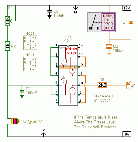
The first circuit energizes the relay when the temperature rises above the preset level. The second circuit energizes the relay when the temperature falls below the preset level. The two circuits are practically identical. The only difference between them...