
JDM pic programmer help required

The JDM PIC microcontroller programmer is a widely used circuit for programming PIC microcontrollers via the RS232 interface. The RS232 communication standard utilizes a set of pins on the PIC microcontroller for receiving serial data. Typically, the relevant pins on the PIC microcontroller include the RX (Receive) pin and potentially other signal lines depending on the specific implementation of the circuit.
In a standard configuration, the RX pin is responsible for receiving the incoming data from the RS232 interface. The signal levels of RS232 are typically inverted compared to TTL logic levels, meaning that a logic high is represented by a negative voltage, and a logic low is represented by a positive voltage. To interface the RS232 signals with the PIC microcontroller, a level-shifting component, such as a MAX232 or a similar RS232 to TTL converter, is often employed. This component converts the RS232 voltage levels to TTL levels that the PIC can interpret correctly.
In addition to the RX pin, the circuit may also utilize the TX (Transmit) pin, which sends data from the PIC microcontroller back to the RS232 interface. Other control signals, such as RTS (Request to Send) and CTS (Clear to Send), may also be involved depending on the complexity of the communication protocol being used.
When designing or analyzing the JDM programmer circuit, it is crucial to consult the specific datasheet for the PIC microcontroller in use, as pin assignments and functionalities may vary between different models. Proper attention to the connection and configuration of these pins ensures reliable communication between the PIC microcontroller and the programming interface.For the following circuit of the JDM pic microcontroller programmer I need information about the PIC microcontroller pins which receive the RS232.. 🔗 External reference
Related Circuits
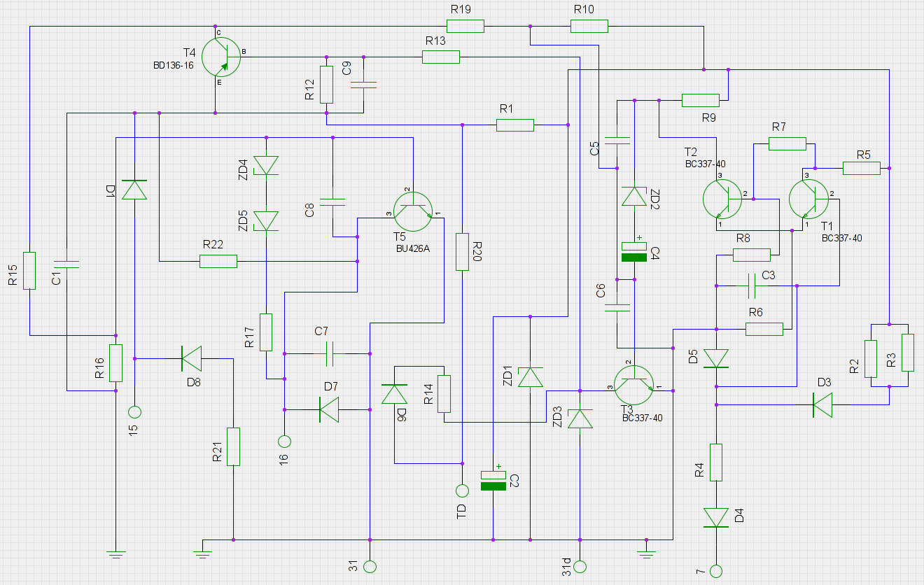
An old ignition module from a 1978 W116 model Mercedes-Benz is being reverse-engineered. The original circuit diagram is not available, so a new one has been created based on the printed circuit board (PCB). The circuit has been assessed...
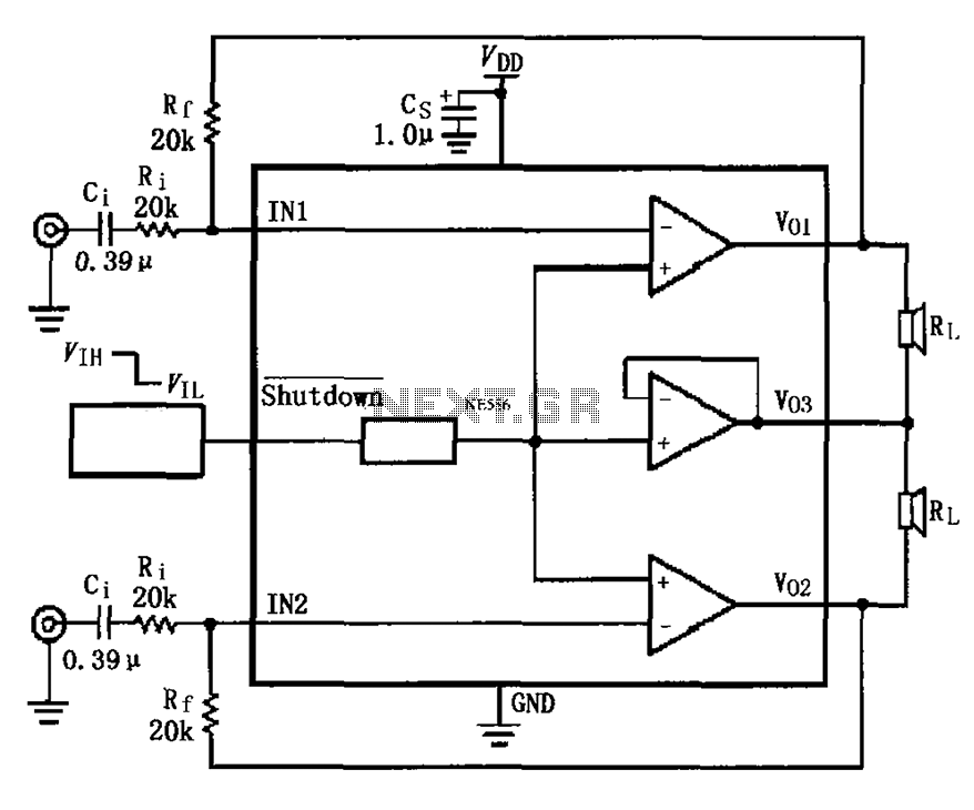
The LM4910 typical circuit is designed for a two-channel amplifier. The left and right channel audio signals are input to the LM4910 (in an MSOP/SO package) at pins 1 and 2. The output signals are delivered from pins 6,...
I found some similar circuits but aren't good enough for me. Some circuits measure the water's resistance to determine the level. That is dangerous for drinking water (contamination) or explosive liquids because electricity is in contact with water. The...
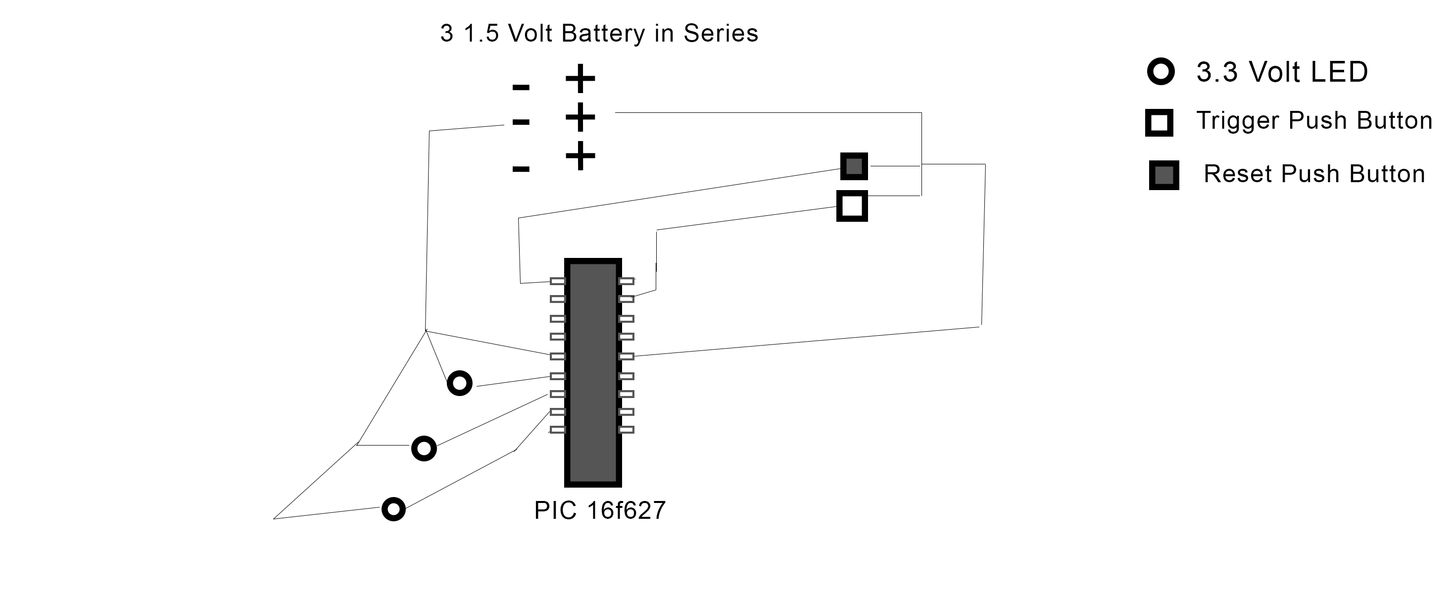
The PIC 16F627 microcontroller has been programmed to activate three LEDs when a trigger pushbutton is pressed. Additionally, when a reset pushbutton is pressed, a shutdown sequence is initiated where each LED turns off sequentially with a 5-second delay...
This project is based on a probe logic states, capable of measuring levels from TTL (5v) to state levels of PLC's (24v). For this we have employed the use of the PIC 12F683 microcontroller, which by its nature is...
The circuit uses a NTE1690 DTMF dialer chip and a PIC16F690 microcontroller. Because this is an IP phone and I cannot just send the DTMF tones over the line, the easiest place to plug in the box is between...