
eprom schematics

The EPROM Emulator serves as a versatile tool for testing and developing electronic circuits that utilize EPROM (Erasable Programmable Read-Only Memory) chips. This device allows engineers and hobbyists to simulate the behavior of EPROMs without the need for physical chip programming, significantly streamlining the development process.
The emulator typically interfaces with a microcontroller or a computer, allowing users to upload binary files that represent the data they wish to emulate. It may feature a user-friendly interface for easy file management and configuration. The circuit design generally includes a microcontroller, memory management components, and communication interfaces such as USB or serial connections to facilitate data transfer.
Key components of the circuit may include:
1. Microcontroller: Acts as the core of the emulator, processing commands and managing data flow.
2. Flash Memory: Provides the storage space for emulated EPROM data, allowing for quick data retrieval and modification.
3. Voltage Regulators: Ensure that all components receive the appropriate voltage levels for optimal performance.
4. Communication Interfaces: Such as USB or serial ports, which enable connection to external devices for data uploading and downloading.
5. User Interface: May consist of buttons, LEDs, or a display to provide feedback and control options to the user.
The design should also include protective features such as over-voltage and over-current protection to safeguard the internal components. Additionally, proper layout considerations should be taken into account to minimize noise and interference, which could affect the accuracy of the emulation.
Overall, the EPROM Emulator is an essential tool for anyone working with EPROM technology, providing a flexible and efficient means of testing and development.Electronic Project Eprom Emulator This EPROM Emulator was designed to compliment the EPROM Programmer (Mark 2).. 🔗 External reference
Related Circuits

Three schematics are available for individuals interested in constructing their own stun gun. For those familiar with reading electronic schematics, the three stun gun circuits presented on this page contain all the necessary information to build a stun gun....

The task involves using a PIC microcontroller to log data from an analog input to an external EEPROM and subsequently sending the collected data back to a PC running MATLAB. An interrupt service routine (ISR) is utilized to read...
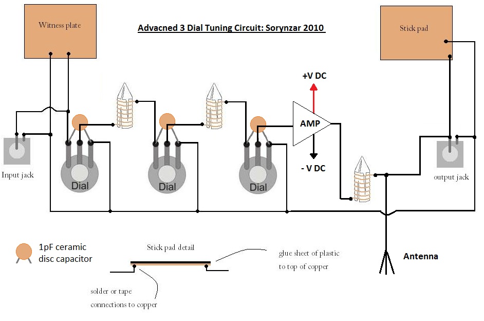
An advanced radionics schematic designed to enhance the power output of a tuning circuit. This schematic outlines a sophisticated approach to improving the efficiency and output power of a tuning circuit used in radionics applications. The circuit typically includes a...

This document discusses a simple project utilizing the 555 timer IC. The 555 timer IC can be configured as an audio amplifier using an astable multivibrator configuration. It performs pulse width modulation (PWM) on an audio signal. The current...
PIC C Compilers are utilized to compile source code, leveraging the extensive built-in functions offered by these compilers. A single C statement can produce multiple pages of PIC RISC instructions, eliminating the need for manual coding. CCS charges $125...
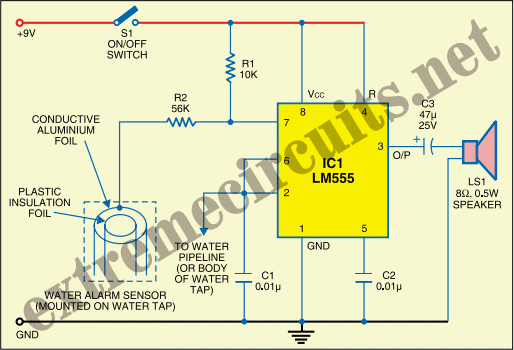
The State Jal Boards supply water for a limited duration each day. The timing of the water supply is determined by management, leaving the public unaware of the schedule. In this context, a water alarm circuit can alleviate long...