
555 timer IC audio amplifier circuit schematics

The 555 timer IC is a versatile component widely used in various applications, including timing, pulse generation, and waveform generation. In this specific application, the 555 timer is configured in an astable mode to create a continuous square wave output. This configuration is particularly useful for audio amplification, where the modulation of an audio signal is required to drive a speaker effectively.
In this circuit, the audio input is fed into the control voltage pin (pin 5) of the 555 timer. By doing so, the amplitude of the output signal can be controlled through PWM, allowing for efficient amplification of the audio signal without the need for complex circuitry. The current output capability of 200 mA ensures that the circuit can drive small speakers effectively, making it suitable for various low-power audio applications.
The capacitor (C3) and diode (1N4007) play crucial roles in the PWM generation process. The rapid discharge of the capacitor enables quick changes in the duty cycle of the output signal, which is essential for effective modulation of the audio signal. The output frequency of approximately 145 kHz is beyond the audible range, ensuring that the speaker responds primarily to the average power delivered by the modulated signal rather than the high-frequency components.
This simple timer-based audio amplifier circuit can serve as an educational tool for beginners in electronics, providing insights into the principles of pulse width modulation, audio signal processing, and the practical applications of the 555 timer IC in real-world scenarios.Here we are going to discuss about a simple timer IC 555 project. The 555 timer IC can be used as an audio amplifierwithastable multivibrator configuration. It functions as to carry outpulse width modulation (PWM) of audio signal. Current(I) capacity of 555 timer amplifier is 200mA which is sufficient to drive a small speaker. This simple 555 IC ba sed amplifier circuit is a good substitute for conventional low power amplifiers. The low frequency audio signal is applied to the control voltage pin (5th pin) of 555 for pulse width modulation (PWM) generation. For beginners who want to know what is PWM `, read simple PWM modulation concept. In the normal mode, we just open circuit the 5th pin (Control voltage pin) of 555 IC. But the most interesting fact we often neglect is that if a low frequency signal is applied to the 5th pin of 555 IC, pulse width modulation starts.
Here the oscillating frequency of 555 astable is approximately 145 KHz. The discharge time of capacitor C3 via diode 1N4007 is too fast since there is no resistor to discharge. The process of pulse width modulation starts and as we know the speaker does not respond to this much high frequency, it responses to the usual DC value of the modulated output.
Hence the audio signal gets amplified. 🔗 External reference
Related Circuits
This tremolo effect circuit utilizes the XR2206 and TCA730 integrated circuits, designed for electronic balance and volume regulation with frequency correction. The circuit is beneficial for stereo channels and can simulate the Lesley effect, also known as the rotating...
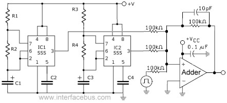
This circuit combines the outputs from two distinct 555 multivibrators using a summing operational amplifier (Op Amp). It serves to illustrate an alternative implementation of a 555 timer, with most background calculations addressed in other sections. The standard configuration...
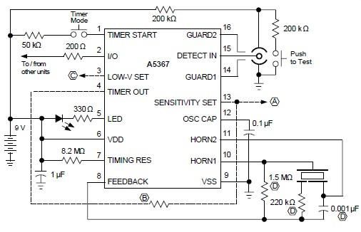
A simple ionization smoke detector with interconnect and timer alarm circuit can be constructed using the A5367 low-current, CMOS circuit, which provides all essential features for an ionization-type smoke detector. This CMOS IC, manufactured by Allegro MicroSystems, includes interconnect...
It was observed that balls were becoming lodged in the ball trough, failing to load into an upkicker or not resting correctly on the trough ball microswitches or optos, which caused the machine to register a missing ball. Initially,...
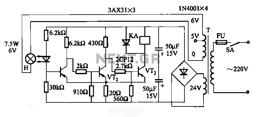
JG series of photoelectric relay circuit. To ensure reliable operation, a Schmitt trigger circuit has been incorporated. These circuits function similarly; when light strikes the photosensitive component, its internal resistance decreases, activating the transistor VT and subsequently energizing the...
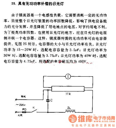
The fluorescent lamp with reactive power compensation operates with a ballast that acts as an inductive load. This inductive load requires reactive power, which leads to a decrease in the power factor of the fluorescent lamp. A lower power...