
Error Compensation Circuit for Pressure Sensor

Offset errors in pressure measurement systems can lead to inaccuracies in the readings, which may affect the overall performance of the system. To address this issue, several circuit designs have been developed. Common methods to eliminate offset errors include the use of differential amplifiers, instrumentation amplifiers, and auto-zeroing techniques.
A differential amplifier can be utilized to compare the output of the pressure sensor with a reference voltage. By amplifying only the difference between these two signals, the circuit effectively cancels out any common-mode noise or offset present in both signals. This approach is particularly useful in applications where high precision is required.
Instrumentation amplifiers are another effective solution for offset error correction. These amplifiers provide high input impedance and excellent common-mode rejection, making them ideal for interfacing with pressure sensors. The design typically includes three operational amplifiers, which work together to amplify the difference between the sensor output and a reference voltage while minimizing the impact of offset errors.
Auto-zeroing techniques involve periodically resetting the output of the sensor to a known value, effectively eliminating any offset. This can be achieved through the use of sample-and-hold circuits that capture the output of the sensor during a calibration phase, allowing for real-time correction of offset errors during normal operation.
In summary, various circuit designs are available to eliminate offset errors in pressure measurement systems, including differential amplifiers, instrumentation amplifiers, and auto-zeroing techniques. Each method has its advantages and is selected based on the specific requirements of the application, such as accuracy, noise sensitivity, and ease of implementation.To obtain an accurate pressure value, we must remove the offset errors. There are? many basic circuit designs that is used to remove the offset errors. This. 🔗 External reference
Related Circuits
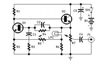
Set R5 to read 1V RMS on an audio millivoltmeter connected to the output with R7 rotated fully clockwise, or to view a sine wave of 2.828V peak-to-peak amplitude on the oscilloscope. An audio amplifier is an electronic device...
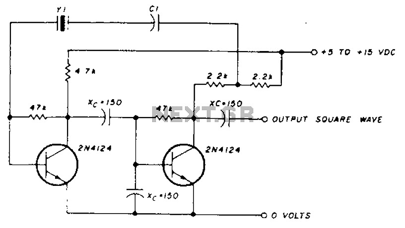
A transistor in series with capacitor C1 can be utilized to adjust the oscillator output frequency. The frequency may vary with changes in capacitance ranging from 20 pF to 0.01 µF, or as determined by the tuning capacitor. The...
Long-distance infrared transmitter circuit diagram. This simple circuit offers a considerable range by utilizing three infrared transmitting LEDs (IR1 through IR3) in series to enhance the radiated power. To further improve directivity and power density, the IR LEDs can...
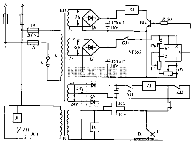
The NE555 timer circuit functions as a vibration generator. The input pin 3 produces pulse frequencies ranging from 5 to 20 Hz. The circuit includes a fan that operates within a bamboo enclosure. The barrel section is designed to...
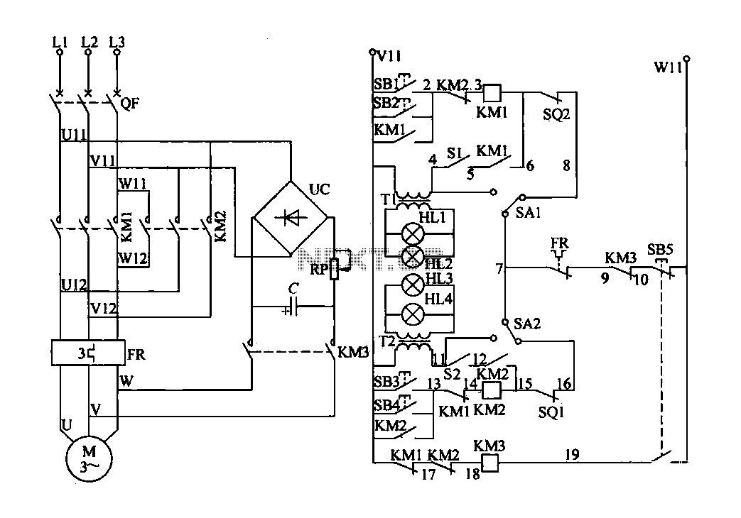
The electric valve control circuit consists of three main parts: the main lines, control lines, and power consumption brake line. The main circuit includes a power switch (QF), three-phase AC contactors (KM1, KM2), a thermal relay (FR), and a...
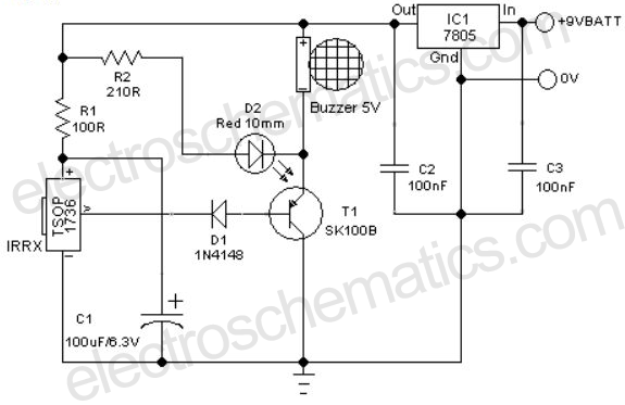
A remote-controlled alarm circuit utilizing the TSOP1736 is designed for easy use by elderly individuals or patients confined to bed. This battery-operated alarm system eliminates the need for routing electric cables to a calling bell switch, making it a...