
ESL amplifier circuit diagram

The described circuit is tailored specifically for Stax Class 1 electrostatic headphones, which require a high-voltage bias to function effectively. The circuit operates within the full audio bandwidth, ensuring that it can reproduce a wide range of frequencies accurately. The transmission voltage of approximately 200 Vp-p is significant as it provides the necessary drive to the electrostatic transducers within the headphones.
The design incorporates a resistor divider network that can be adjusted to achieve different bias voltages. While the standard configuration uses a DC bias of 200 V, the flexibility to increase this to 400 VDC allows for compatibility with various models of Stax Class 1 headsets, which may have differing bias requirements. This adaptability is crucial for users who may own multiple headphone models or require specific operational parameters.
In practical implementation, the circuit should be constructed with high-voltage rated components to ensure reliability and safety during operation. Proper layout and shielding techniques are also recommended to minimize noise and interference, which can adversely affect audio quality. Additionally, attention should be given to the power supply design, ensuring it can deliver the necessary voltage and current without introducing fluctuations that could impact performance.
Overall, this circuit design provides a robust solution for driving Stax Class 1 electrostatic headphones, accommodating their unique operational needs while delivering high-fidelity audio.When connected to popular Stax Class 1 electrostatic headphones, the design shown in the figures may be on the full audio bandwidth transmission close 200Vp-p voltage. Although you can change the .png">resistor divider to provide a bias voltage of up to 400VDC, the figure shows the use of a DC bias to 200V. Noting that many kinds of Stax Class 1 headset have a similar demand-driven and biased, so this design is also applicable to these models.
Related Circuits
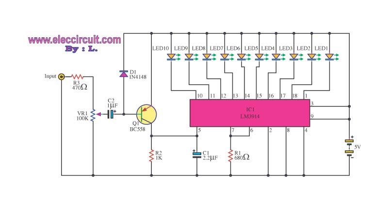
This is a simple light-running circuit synchronized with music. The circuit is straightforward, operating in mono, and requires only a few components. It can be connected to the output of a CD player. The described circuit utilizes a basic audio...
Full sine wave UPS information in English, along with detailed C language source code. English proficiency may be a concern, so caution is advised. A full sine wave Uninterruptible Power Supply (UPS) is designed to provide a stable and continuous...
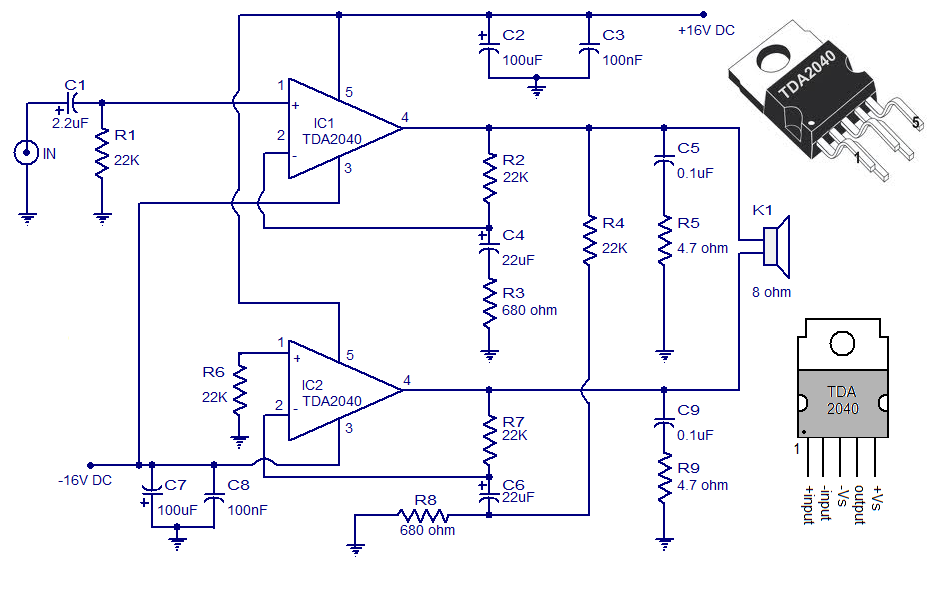
A 30 Watt audio amplifier circuit utilizing the TDA2040 is illustrated here. The TDA2040 is a class AB monolithic integrated audio amplifier available in a Pentawatt package. This integrated circuit features low harmonic distortion, minimal crossover distortion, and includes...
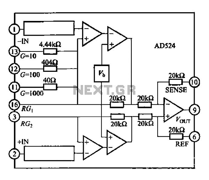
The AD524 is a low-drift instrumentation amplifier characterized by a drift voltage of 0.5 mV and a maximum drift of 25 mV at room temperature. It has low noise performance with a noise level of 0.3 mVp-p in the...
The foot 13 between valve value 1 and valve value 2 will draw the transistor base current. If the relay releases, after a recovery time of 0.5 seconds, pressing the key will initiate the switching process again. The timer...
Most of the power supply failure indicator circuits need a separate power supply for themselves. But the alarm circuit presented here needs no additional supply source. It employs an electrolytic capacitor to store adequate charge, to feed power to...