
Esquire Wiring

To create a comprehensive electronic schematic description, it is essential to focus on the wiring layout, components involved, and potential troubleshooting approaches. A typical wiring schematic includes a clear representation of the circuit elements, such as resistors, capacitors, diodes, and integrated circuits, along with their connections.
In this scenario, the wiring is suspected to have issues stemming from human error. This could involve incorrect connections, misplaced components, or inadequate soldering techniques. A methodical approach to troubleshooting is recommended. This includes visually inspecting the circuit for any loose connections or shorts, using a multimeter to verify continuity and resistance values, and ensuring that all components are correctly oriented and rated for the intended application.
Additionally, documenting the circuit with clear labels and annotations can aid in identifying potential problem areas. Utilizing software tools for schematic design can enhance clarity and ensure that the wiring conforms to standard practices. By providing detailed images and descriptions of each section of the circuit, it becomes easier to pinpoint and rectify any wiring mistakes, ultimately enhancing the reliability and functionality of the electronic system.and the most likely problem with my wiring is ME. My apologies for the long post but I thought the more information and pictures I can provide the.. 🔗 External reference
Related Circuits
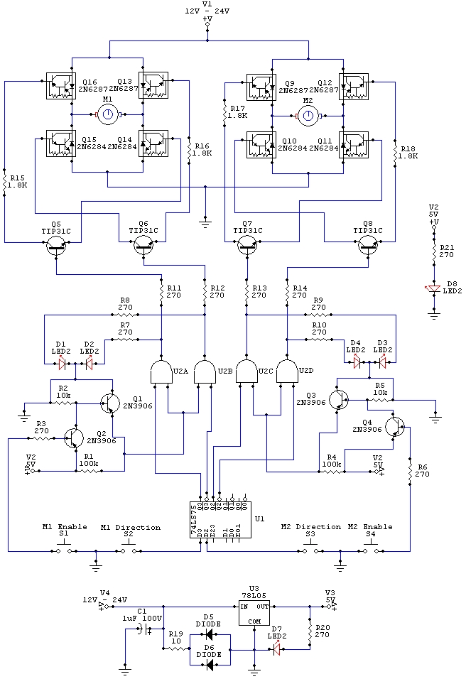
The wiring schematic played a significant role in the robot. This diagram is used to graphically display all the wiring of the motor-controlling micro-components that enabled the robot to physically move forward, backward, left, right, and stop. This diagram...
While the normal PC hardware might well run with just Tx, Rx and Ground connected, most driver software will wait forever for one of the handshaking lines to go to the correct level. Depending on the signal state it...
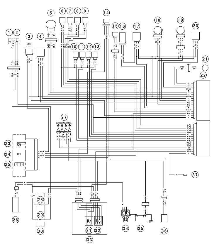
The entire setup was removed from a bike some time ago and functioned properly then. It also operated well approximately a year ago on the engine stand where it is currently mounted. Recently, when attempting to start the engine...
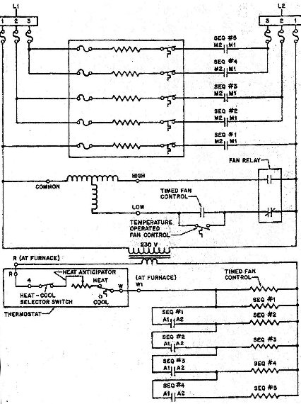
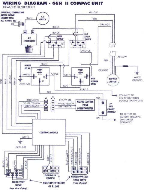
This diagram allows for easy identification of test points related to Applied Voltage and Potential Voltage. For instance, by isolating one of the heating elements, an N.O. (Normally Open) switch can be observed wired in series with it. The...
Mercury, Oldsmobile, Plymouth, Pontiac, muscle cars, and antique classic car wiring diagrams are continuously being added to this site. The wiring diagram for the Porsche 911L engine from the 1968 model has undergone changes since the original scheme. For...
1996 Isuzu Rodeo Headlight Wiring Diagram. The 1996 Isuzu Rodeo headlight wiring diagram provides a detailed representation of the electrical connections and components involved in the vehicle's headlight system. This diagram is essential for understanding how the headlight assembly operates...