
Ethernet remote device controller sensor circuit

The circuit utilizes the ENC28J60 Ethernet controller, which provides a robust interface for network communications. The microcontroller, an Atmega88, is programmed to handle UDP packets, allowing for efficient command transmission and relay control. The design focuses on a half-duplex communication mode, which is suitable for applications with low traffic, thereby optimizing performance and minimizing the complexity of the circuit.
The inclusion of LED-B serves as an indicator of the operational status of the ENC28J60. Correct polarity is essential for proper functionality, as incorrect connections could lead to malfunction. The relay, connected through CONN3, is driven by the microcontroller's GPIO pin, enabling it to switch on or off based on received commands.
Diode D1 is a critical component in this circuit. It is placed in parallel with the relay coil and is oriented to allow current to flow in the reverse direction when the relay is deactivated. This action prevents voltage spikes, known as back EMF, which can occur when the relay coil is de-energized. Such spikes could potentially damage the microcontroller or other sensitive components within the circuit.
Overall, the design is aimed at providing a reliable and efficient means of controlling a relay through network commands, with considerations for both hardware protection and software efficiency. Future enhancements, such as TCP implementation, could further expand the functionality of this device, allowing for more versatile control options, including web-based interfaces.The main purpose is to show here the circuit diagram and explain the software. We use a UDP application to send commands to the microcontroller. Those commands will then cause the microcontroller to switch on or off the relay. It think it will be possible to even implement TCP. The current UDP software is less than 3k bytes and that is not even half of the memory on an Atmega88. TCP would then allow us to control the device via a web browser. I have however not tried it yet. Here is the circuit diagram. Most of it is very straight forward and standard for the ENC28J60. The polarity of LED-B is important as it determines the duplex operation of the chip. Standard Half-duplex is what makes most sense for a device which will send and receive only rather little traffic. A relay can be connected to connector CONN3. Note the diode D1. It is not useless and it is not the wrong way round in the circuit diagram even though it looks like that.
It is there for those who plan to connect a small 6V relay on that output. It protects the whole circuit against the possibly very high voltages which can be induced by the coil of a relay. 🔗 External reference
Related Circuits
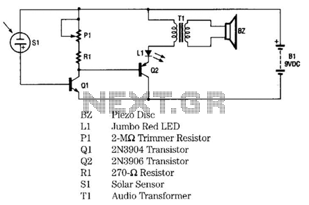
The infrared remote-control tester employs a sensitive PN-type solar sensor directly connected to a Darlington amplifier composed of transistors Q1 and Q2. Biasing is achieved through resistor R1 and PI, a variable resistor that functions as a sensitivity control....
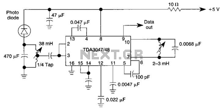
The circuit operates from a 5-V supply and has a current consumption of 2 mA. The output functions as a current source that can drive or suppress a current exceeding 75 mA with a voltage swing of 4.5 V....
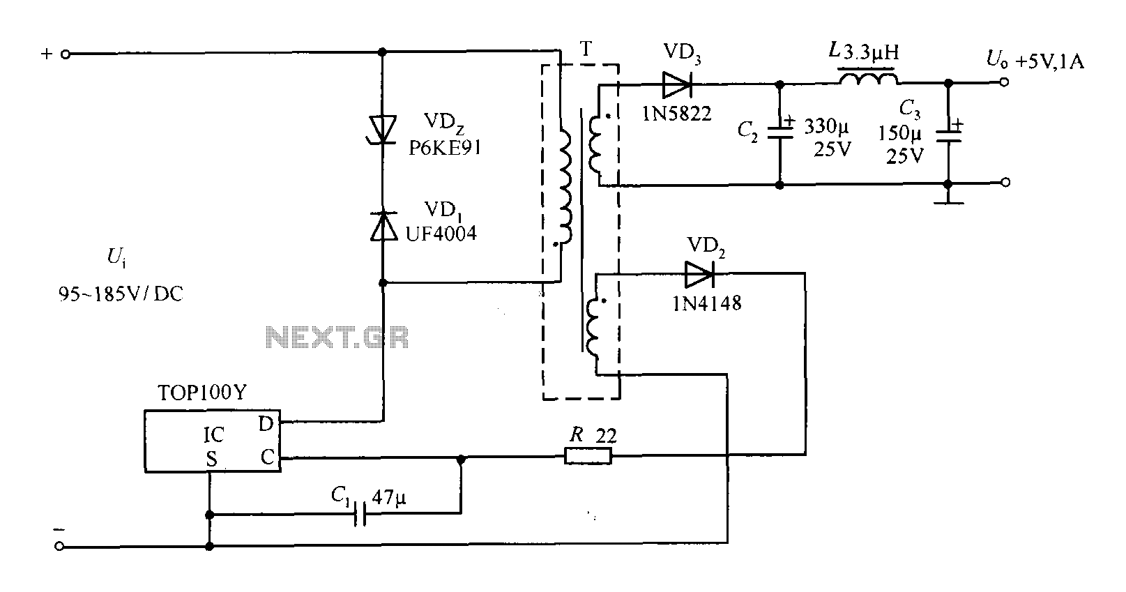
The TOP100Y is a flyback DC switching power supply circuit with a +5V, 1A output. This power supply features a feedback circuit that directly regulates the output voltage, making it suitable for applications that require electrical isolation and minimal...
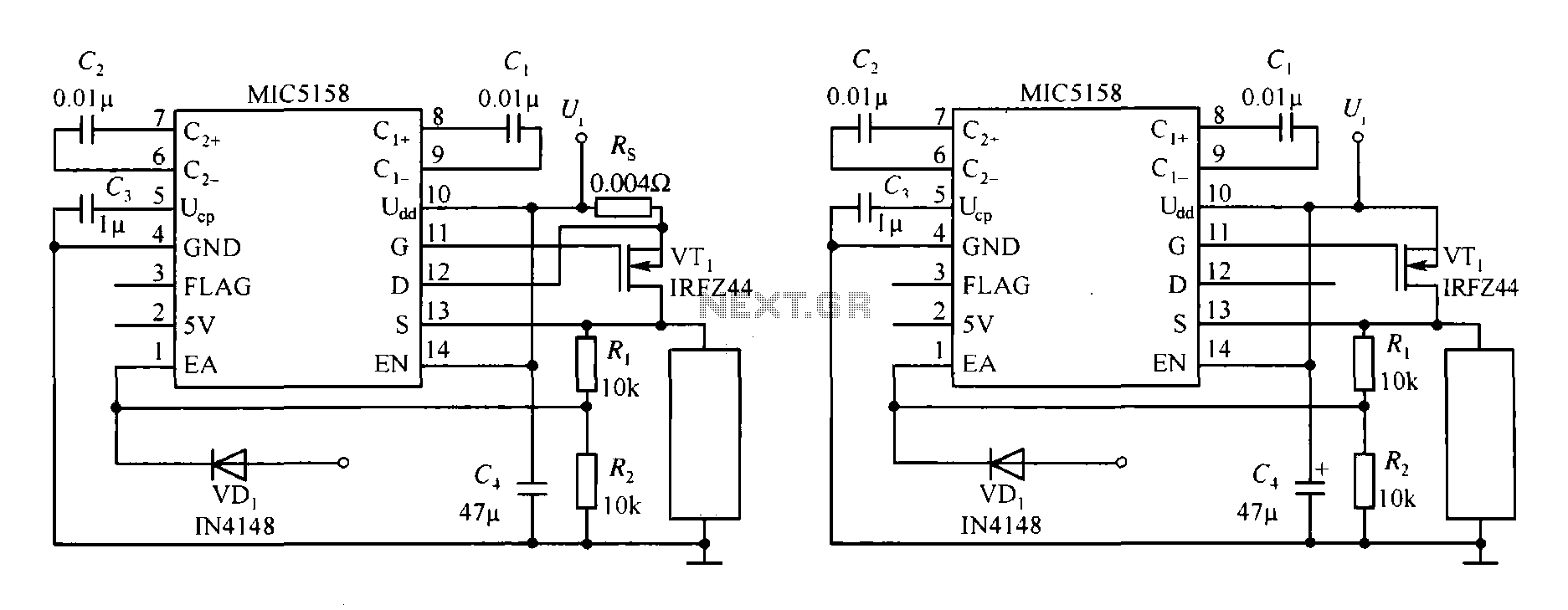
The MIC5158 is part of a high-speed switching circuit diagram that focuses on the rising edge. The MIC5158 is a precision voltage reference and high-speed switching device that is commonly utilized in various electronic applications requiring rapid signal transitions. In...
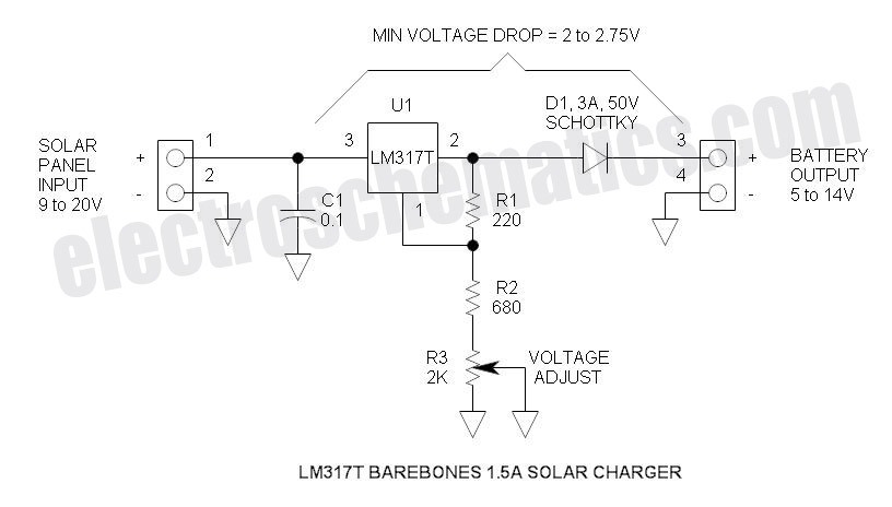
This solar battery charger is a simple and cost-effective project suitable for hobbyists. While it has some limitations compared to other similar devices, it offers several advantages. The charger is designed for lead-acid batteries but can also charge any...
The receiver is based on a basic SA612 circuit. The local oscillator (LO) for the 20-meter band operates at approximately 9 MHz, with an intermediate frequency (IF) of 5.068 MHz. The IF filter employs two crystals and has a...