
EXPERIMENTAL DATA TRANSMITTER FORFIBER OPTICS

The experimental data transmitter circuit is designed to facilitate the transmission of data through optical fibers using a laser diode as the light source. The CD4093 integrated circuit, which consists of four NAND gates, is employed to generate the necessary square wave signal that drives the laser diode. This IC is known for its versatility and ability to operate at low power, making it suitable for various applications in optical communication systems.
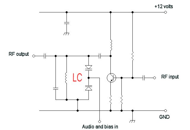
The oscillator circuit is configured to operate at a frequency of approximately 3 kHz, which is suitable for certain types of data transmission. The frequency can be fine-tuned by adjusting resistor R5, which is part of the timing network. This adjustment is crucial as it ensures that the modulation frequency aligns with the characteristics of the laser diode being used, optimizing the performance of the transmitter.
The optical fiber used in this setup serves as a medium for transmitting the modulated light signal generated by the laser diode. The choice of optical fiber should be compatible with the wavelength of the laser diode to ensure minimal signal loss and optimal data integrity. The circuit is designed to be compact and efficient, allowing for easy integration into various experimental setups where data transmission is required.
Overall, this schematic provides a foundational approach to building a basic optical data transmitter, suitable for experimentation and further development in optical communication technologies.This schematic for an experimental data transmitter uses optical fibers and a laser diode. Trans-mission frequency of the free-running oscillator is approximately 3 kHz. R5 might have to be varied to suit your laser diode. IC1 is a CD4093.. 🔗 External reference
Related Circuits
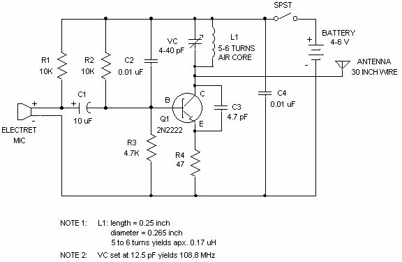
Wireless FM Transmitter. The site provides some explanation on how the circuit operates; however, there are uncertainties regarding certain components, including the electret microphone and the frequency modulation process. The electret microphone operates at a current of 200 µA,...

This 3V FM transmitter circuit is one of the simplest and most effective basic transmitters, offering a commendable transmitting range. It is remarkably powerful considering its small component count and 3V operating voltage. It can easily cover over three...
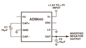
The ADM660 is a charge-pump voltage converter that can either invert the input supply voltage or double it. The schematic below depicts the ADM660 Voltage Inverter Circuit Configuration Diagram. This inverting schematic is ideal for generating a negative rail...
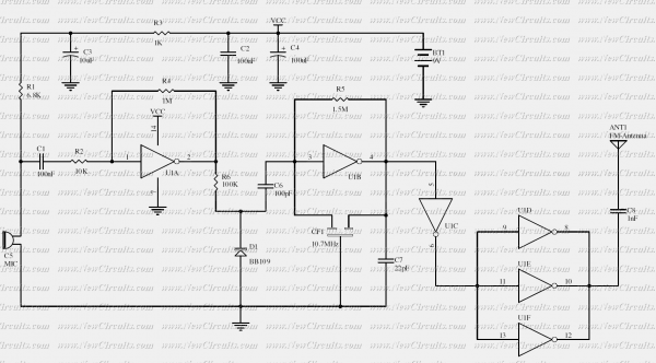
The RF oscillator using the inverter N2 and 10.7MHz ceramic filter is driving the parallel combination of N4 to N6 through N3. Since these inverters are in parallel, the output impedance will be low so that it can directly...
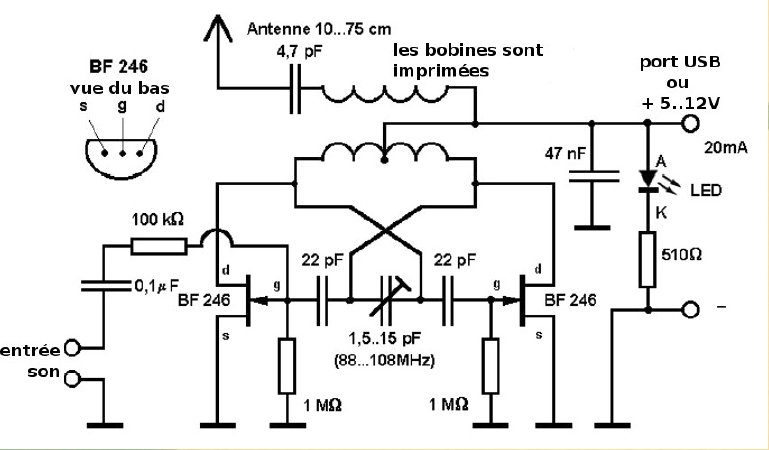
Here is a small FM transmitter circuit designed for desktop or laptop use, allowing users to enjoy movies and music from a distance. This USB-powered FM transmitter connects to a computer or MP3 player and broadcasts on a tape...
For a fixed frequency transmitter, a common method is to use a resonant quartz crystal in a crystal oscillator to establish the frequency. In transmitters where the frequency must be variable, several options are available. It is often the...