
Experimental I/O board for microcontrollers

The general-purpose I/O board serves as a versatile platform for various electronic projects, particularly beneficial for those new to electronics. The board's architecture allows for easy integration of commonly used components, facilitating rapid development and experimentation. The LM7805 voltage regulator is crucial, providing a stable +5 V output that ensures reliable operation of the connected devices.
The inclusion of the HD44780-based LCD enhances the board's capability by enabling visual output. The pin configuration for the LCD is designed to be user-friendly, with dedicated female headers for easy connections. This setup not only simplifies the wiring process but also allows for quick replacement or upgrades of the LCD module as needed.
The potentiometer for contrast adjustment is a valuable addition, giving users the ability to optimize the display visibility based on ambient lighting conditions. The four tact switches and LEDs provide basic interactive elements, allowing for user input and visual feedback, which are essential for debugging and testing.
The integration of the LM34DZ temperature sensor expands the board's functionality, enabling temperature monitoring in various applications. Coupled with the I2C compatible EEPROM (24LC512), the board can store configuration settings or data logs, enhancing its application in projects that require persistent data storage.
The design emphasizes modularity and expandability, with ample prototyping space available for additional components or custom circuits. This flexibility makes the board suitable for a wide range of projects, from simple educational tools to more complex embedded systems.
The circuit schematic illustrates the simplicity of the design, where each component operates independently while sharing the same power and ground connections. This straightforward approach minimizes complexity and potential errors during assembly, making it an ideal choice for beginners and experienced users alike.If you are a newbie and having the similar experience, here I suggest a general purpose I/O board that will not only reduce your prototyping time but also free up plenty of space on the breadboard for your project. The construction of this board is very simple. You can solder basic I/O devices of your choice (that you use more frequently) on a gen eral purpose perforated board and provide access to them through headers. The board that I constructed is shown below. It has got an LM7805 IC that provides a regulated +5 V power supply to rest of the devices on the board. A 16-pin female header is a plug-in for an HD44780-based alphanumeric LCD. The four data pins (D4-D7) and two control pins (Register Select, RS, andEnable, E) of the LCD are accessible through female headers, as shown on the bottom left part of the board.
A potentiometer is also available on the board to adjust contrast of the display. Four tact switches, four LEDs, and one coil buzzer serve as basic input and output devices. In this particular version, I have also added a LM34DZ temperature sensor device along with an I2C compatible serial EEPROM (24LC512). There`s plenty of prototyping space available for extending the functionality of the board in future.
The circuit diagram of this project is very simple. There is nothing special as each component is independent and is not connected to any other component. The only common thing in them is all of them share the sameVcc and Gnd terminals. I have provided the following schematics for reference purpose. 🔗 External reference
Related Circuits
Many versions of VCXOs exist, and this is the final version selected for all future VCXO implementations. It is highly versatile for all frequencies, accommodating up to the 7th overtone of crystal oscillators that can be utilized in VCXOs....
U1 is a Complex Interface Adapter (CIA). Both parallel ports are utilized to decode the keyswitches on the keyboard. Parallel port A signals (PA0 - PA7) function as outputs, while parallel port B signals (PB0 - PB7) serve as...
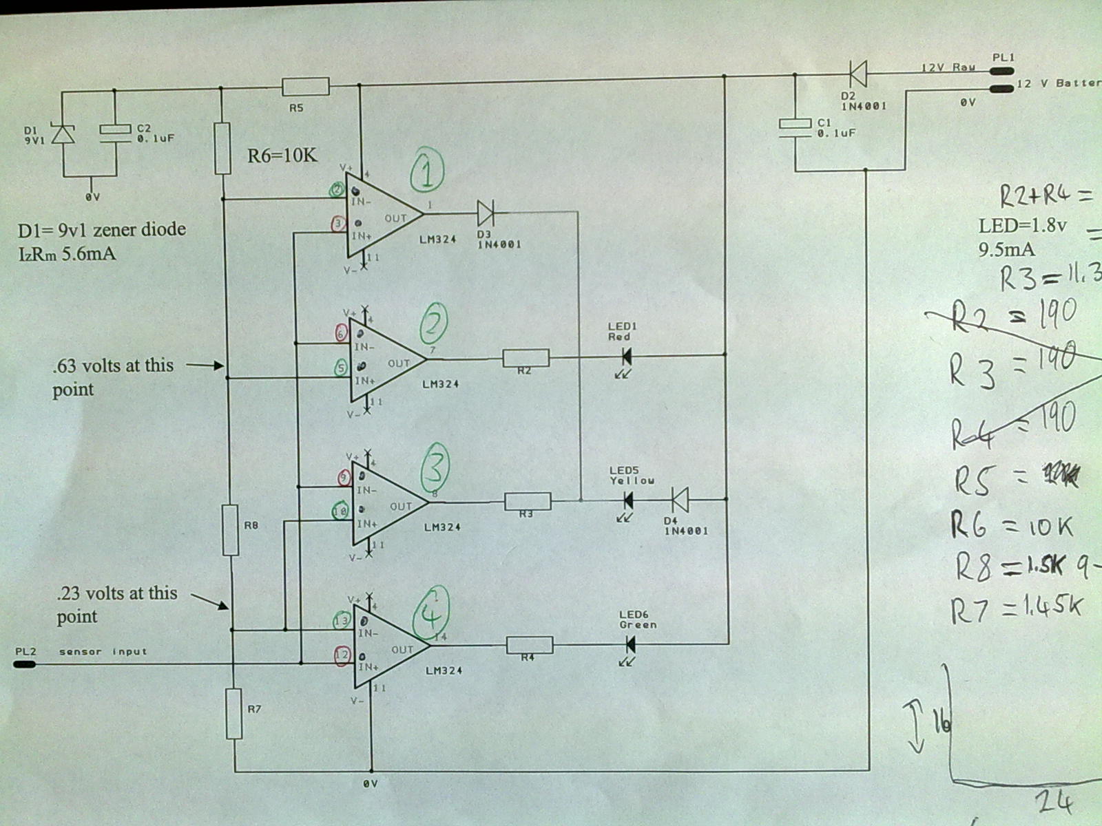
A 12V power supply is connected to the positive terminal, allowing current to flow through a protection diode and a capacitor that smooths the voltage. A zener resistor (R5) limits the current to the zener diode, which regulates the...
A do-it-yourself Atmel STK505 replacement board facilitates the programming of ATtiny84 and ATtiny861 AVR microcontrollers (14-pin and 20-pin) using the STK500 development kit. The article also details a quick setup connector board for the ATtiny 8-pin microcontroller. The Atmel STK505...
The page is about equipping an Atmel AVR microcontroller based system with a Prism WLAN interface. This document is intended for people that already have experiences with the AVR microcontrollers and teaches them how to add a cheap but...
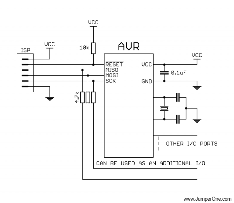
This schematic illustrates the placement of a decoupling capacitor on the right side, which should be positioned as close as possible to the power pins of the microcontroller. It includes a crystal oscillator, which is optional; an internal RC...