
VCXO Boards

The VCXO (Voltage-Controlled Crystal Oscillator) circuit described is designed to provide precise frequency control over a wide range of applications. The core of the design is based on the use of a crystal oscillator capable of operating at various frequencies, including the higher overtone frequencies, which enhances the stability and accuracy of the output signal. The integration of a second phase-locked loop (PLL) synthesizer on the CPLD (Complex Programmable Logic Device) board allows for real-time lock detection, which is crucial for maintaining frequency stability.
The use of an LED to indicate the lock status is a practical feature that allows for immediate visual feedback regarding the operation of the VCXO. The CD74HC7046AM device serves as a highly efficient PLL, enabling the circuit to achieve the desired frequency with minimal additional components. This device's low additional cost makes it an attractive option for designers looking to enhance the functionality of their VCXO circuits without significantly increasing the overall expense.
The new CPLD PLL board is designed to be user-friendly and adaptable, accommodating the 74HC7046 to meet the demands of various applications. This adaptability is essential in modern electronic design, where flexibility and performance are paramount. The board layout will include necessary connections and components to ensure seamless integration of the PLL, thereby improving the overall performance and reliability of the VCXO system.Many versions of VCXO`s this is the final version I have decide to use in all VCXO`s in the Future, it is extremely universal at all Freq. up to 7th Ovetone XTAL`s that can be used in VCXO. NOTE: On this CPLD PLL Board I am using a second Phase Lock Synthesizer to indicate Lock by driving a LED device.
The additional cost using thet CD74 HC7046AM device is very little, and it can also be used as the PLL as well with a very few extra components. Most People are asking that this Device be Installed as well, as a result the New CPLD PLL Board being professionally produced will include facilities to accomidate the 74HC7046.
🔗 External reference
Related Circuits
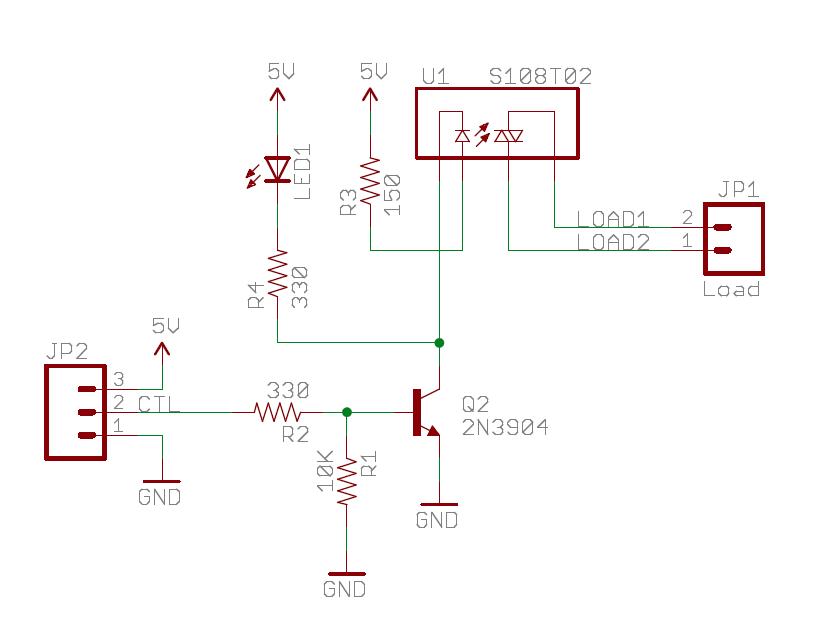
The Sparkfun Solid State Relay (SSR) Breakout Board operates similarly to a traditional relay but utilizes semiconductors for switching. It is powered by the mbed VU 5V supply and is compatible with any mbed digital output pin. The schematic...
Attached are three captures from a L297/L298 board using the same motor at 500, 750, and 900 steps per second on a 36V supply, wired in bipolar parallel (coil resistance = 3.2 ohms). This shows the A-enable signal (blue)...
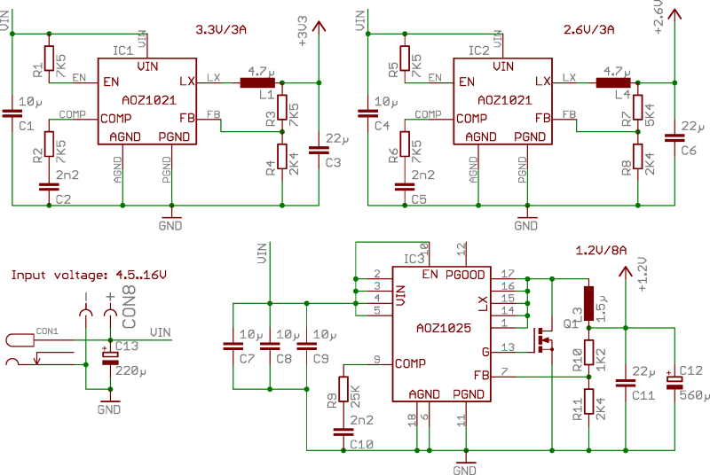
ZTEX USB-FPGA Boards require three different voltages: 1.2V, 2.5V-2.6V, and 3.3V, which must be supplied externally. This can be achieved using Power Supply Modules, Experimental Boards, or a user-specific design. To facilitate development in the latter scenario, three reference...
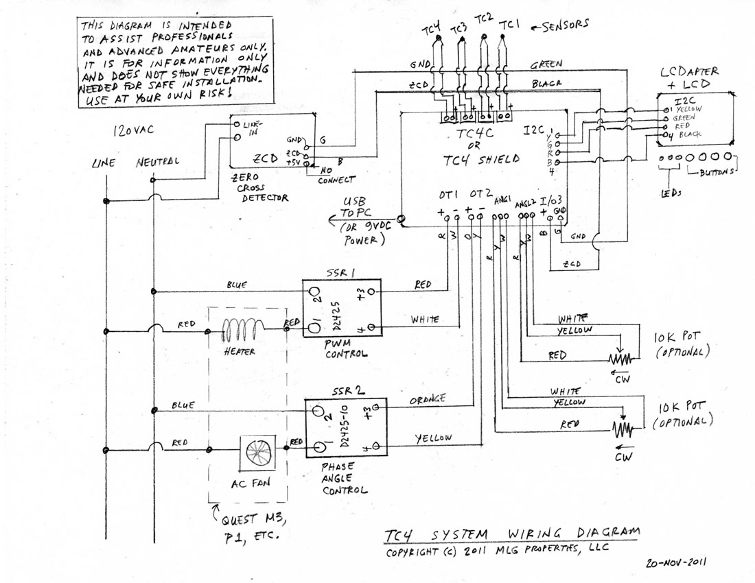
This is a complete standalone system compatible with Arduino Uno, which will be fully assembled, tested, and programmed prior to shipping. Users can select from various TC4 applications to be pre-programmed into the board. For those who wish to...
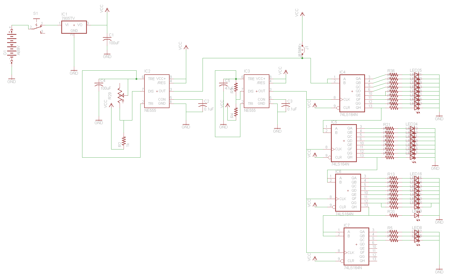
For the two-layer board schematic, six core integrated circuits (ICs) will be utilized: four 74LS164 shift registers and two 555 timers. The schematic will be constructed using the Eagle Layout Editor, as all required components are available in its...
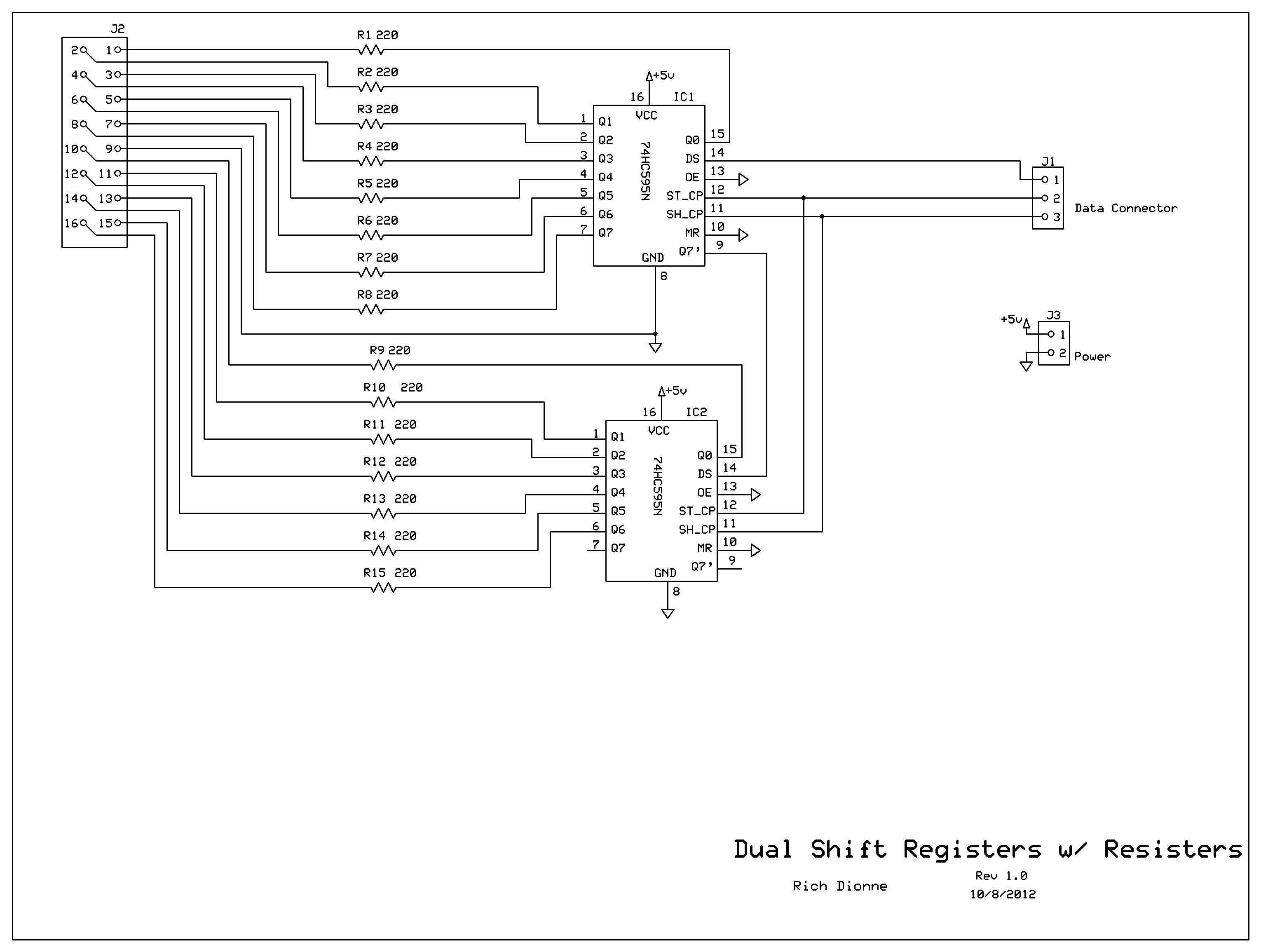
Control the two digits representing minutes; this circuit includes two shift registers, 30 resistors, and 30 LEDs. The schematic illustrates the design. As the circuit design neared completion, it became evident that soldering all components onto a basic prototyping...