
Experimental Pendulum Clock

The rod extends some 15 cm below the bob and is fitted with large washes at the lower end. Note that for a pendulum to beat in seconds, there must be 99. 4cm distance between the support and the centre of mass of the pendulum. Between the bob and the lower end is a 5mm wide white reflector facing back. Below the rod and 15mm to the left is the impulse solenoid, with a core but no actuator attached. The circuit comprises of four parts: (1) the sensor; (2) the counter and solenoid driver; (3) the clock driver; and (4) the clock. The sensor is built on its own small piece of strip board and is located on the centre line of the backboard behind the reflector.
It utilises a Sharp IS471F infrared modulated detector (Farnell cat. 414-2860) to eliminate interference from external light sources. The infrared emitter (IRLED1) must be mounted near to the detector (IRDET1) but be masked from it. The emitter radiates a coded signal toward the reflector. As the pendulum passes the centre line it reflects the signal back to the detector, which then gives a negative-going output pulse on pin 2. This makes the surface-mount LED (LED1) flash once. It also sends a signal to the counter and clock driver circuits on the main circuit board. Pulses from the sensor are fed into IC1, a 4020 14-stage ripple counter. The counter`s output (pin 6) goes high every 128 counts (seconds). These long duration pulses are inverted by transistor Q1 and differentiated by the 10nF capacitor and 22kO resistor, providing a narrow trigger pulse for a 7555 CMOS timer (IC2).
The 7555 is wired as a monostable, driving the base of transistor Q3 with a relatively short pulse width suitable for energising the impulse solenoid. LED2 flashes in unison with solenoid pulses, and can be mounted right on the solenoid as a visual aid.
Pushbutton switch S2 is used to provide gentle starting pulses to get the pendulum swinging smoothly at the outset. Switch S1 resets the counter to zero. With this arrangement, the pendulum is set swinging and when it is to the left of centre, S1is pushed.
Thus, the pendulum moves right to left on even numbered counts. At the 128th count, the solenoid gives a shot pull to the left just as the pendulum is passing through the centre line and moving right to left. The distance of the solenoid below the pendulum is adjusted so that it does not jerk the pendulum but adds a gentle nudge.
The clock driver circuit also derives its timing from the output of the sensor. Negative-going pulses from the sensor are inverted by Q4 before being fed into a 4013 flipflop. On the output side, pins 12 & 13 go high in turn for one second. These pulses are too long to directly drive the clock coil, so they`re logically "anded" with the short pulses from the sensor using two gates of a 4093 NAND Schmitt trigger (IC4). The outputs from these gates then drive an adapted quartz clock movement. A suitable clock can be made from a standard quartz movement by isolating the coil and removing the battery.
See SILICON CHIP, Dec. 1996, page 38 for full instructions or October 2001 page 37 for brief notes. This is an experimental clock so you may have to try various solenoids to find one that works for you. If necessary, the solenoid pulse duration can be changed by varying IC2`s timing components. If the suspension is too stiff, try impulsing at 64 beats from pin 4 of IC1, but note that the aim is to get the freest pendulum movement possible.
The Synchronome and Hipp clocks were impulsed at 30-second intervals, so your clock could be even better. In the prototype, the reflector was made from the back of an adhesive cable clip snapped on to the pendulum rod.
The white back was masked to give a 5mm wide central vertical strip, giving clean, short pulses as the pendulum passes. Current drain is several milliamps, so the prototype was powered from an SLA battery fed from a float charger.
A pendulum beating in seconds is called a Royal pendulum. Its length is the same as one in a typical long case (grandfather) clock. 🔗 External reference
Related Circuits
A mechanism allows a standard potentiometer to function as a digitized potentiometer, converting each setting into a number between 0 and 15. This information is utilized to determine the duration for each step. An analog-to-digital converter (ADC) is designed...
This is a voltage controller oscillator that was designed as a wide range oscillator to generate clock pulses for a stepper motor drive system. It does however have some interesting features. The original application used a stepper motor for...
A clock utilizing numeric neon lamps, commonly referred to as nixies. These display devices were prevalent during the 1960s and 1970s, but their usage declined with the advent of LED displays. Today, nixies have become sought-after collectibles and are...
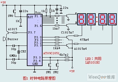
The circuit design incorporates an anodic Nixie tube for the LED display. It utilizes the LQ5101BS general luminous diode, with the driving transistor being either the 2SA1015 or 2SC1815 types, which are readily available. Additionally, low-power transistors such as...
The Multimeter Clock consists of three multimeters, the first meter displays hours, the second displays minutes and the last displays seconds. A 16F628A PIC microcontroller keeps track of time and outputs a calculated current to each meter to display...
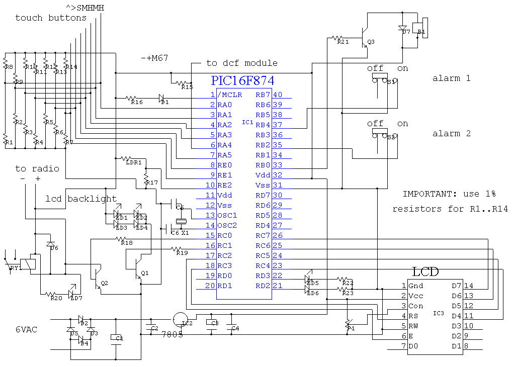
The program utilizes the built-in analog-to-digital (AD) converter of the PIC16F874 microcontroller for sensing touch buttons. The PIC features eight AD ports, with seven designated for the touch buttons and one for light measurement. To receive DCF signals, a...