
Nixie clock I Vintage electronics
The nixie clock circuit employs a combination of vintage and modern components, creating a unique blend of historical technology and contemporary design practices. The nixie tubes, known for their distinct glow and retro aesthetic, require a high voltage supply to operate effectively. This is typically achieved through a transformer that steps up the mains voltage to the necessary level for the nixies, while the selenium rectifier converts the AC voltage to DC for stable operation.
The use of 74xx TTL ICs is significant, as these were foundational in early digital electronics, providing the necessary logic functions to decode and drive the nixie displays. The 9315 IC serves as a decoder and driver for the nixies, translating binary input signals into the appropriate control signals that illuminate the correct segments of each tube. The 7490 ICs function as decade counters, allowing for the counting and display of time in a human-readable format.
The current limiting resistors are critical in protecting the nixie tubes from excessive current, ensuring a longer lifespan for these delicate components. The design must also account for the thermal management of the circuit, as the components can generate heat during operation. The transparent box not only serves a functional purpose by providing cooling airflow but also allows for visual appreciation of the vintage technology within.
Safety considerations are paramount in the design of this clock. The live chassis design requires careful isolation of all high-voltage components to prevent accidental contact. The enclosure must be robust and compliant with electrical safety standards to mitigate the risks associated with high voltage. Additionally, the use of appropriately rated components for mains voltage operation is crucial to ensure the reliability and safety of the device.
This nixie clock project not only serves as a functional timekeeping device but also as a tribute to the ingenuity of early electronic design, showcasing the aesthetic and technical characteristics of vintage electronics in a modern context.A clock using numeric neon lamps, also known as nixies. These display devices were common around the sixties and seventies and their use fell off after the invention of LED displays. Nowadays nixies have become valuable oldies and are hard to get even tough they are still being manufactured in very small quantities.
This project was made possible by Estebitan and Miguel Gimenez. Estebitan sent me an old counter consisting of three nixies and some old 74xx TTL ICs, components I have reused for this clock. Miguel Gimenez gave me a fourth nixie. Thank you very much! Whenever possible I have used original components and circuit design common in the seventies so this clock keeps that vintage electronics style.
I have had to add some new components. The clock is mounted in a transparent box of chocolates drilled to screw the board and nixies and to let in air flow for cooling. At the right side on the back you can see push buttons to set the time. Some of the 74xx ICs come from an old counter and are original TTL chips from early seventies. They are labeled with their manufacture date: three 9315 decoders and nixie drivers at top row are dated 7327 (June 1973), two 7490 at second row left and right are dated 7205 (February 1972) and use ceramic package and a 7490 at third row right is labeled 7236 (September 1972) with gray plastic package.
All of them were manufactured by Fairchild, draw around 20mA and get warm. 9315 IC is a variant of standard 7441 TTL IC (decoder and nixie driver), manufactured by Fairchild and pin compatible, the only apparent difference are its outputs under over-range values (10 to 15). More information here:. Also I have reused the current limiting resistors, nixie sockets, wires and an old BC107A transistor with gold plated pins and plastic package (uncommon as this transistor has been always in a metal can).
From another old board I got a selenium rectifier AEG model B20C450 and a 1000 µF 10V Bianchi capacitor that form its power supply. Just like many vintage electronic circuits from that era this clock is designed around a live chassis.
This type of design is not meant for playing or experimenting with circuits, instead it is meant to be built and enclosed in an isolated case before power is applied for the first time. In this design a live circuit provides a simple, cheap and effective way to get the necessary high voltage to lit the nixie tubes with only a few components.
The drawback is you must keep in mind and carefully follow these safety warnings: The circuit presented below works connected directly to mains power, so any part, wire, solder and node is under dangerous voltages that can cause injury or death if touched. The entire clock circuit including nixies, buttons for setting time, transformer and other parts are subject to hazardous voltages and they must be enclosed in an electrically isolated case so that all mentioned parts are unreachable from the outside.
Push buttons for setting the time must be approved for operation at mains voltages of at least 250V AC, must be fully isolated and must be mounted according to their safety rules outside the isolated case. Under no circumstances you should attempt to measure any part of this circuit while plugged to mains.
Never forget that all parts of this circuit are under dangerous voltages with respect to earth ground and either mains pole. Remember the ground probe of a scope or digital analyzer, if powered from mains, is connected to ground, therefore never attempt to connect it to any part of this circuit otherwise you would cause a short circuit.
This circuit works connected directly to mains power and has the same dangers as working on any other electrical live circuit or mains installation. The same procedures, precautions and hazards apply to this circuit. Note this circuit has no filter capacitor for nixie supplies therefore when unplugged it does not s 🔗 External reference
Related Circuits
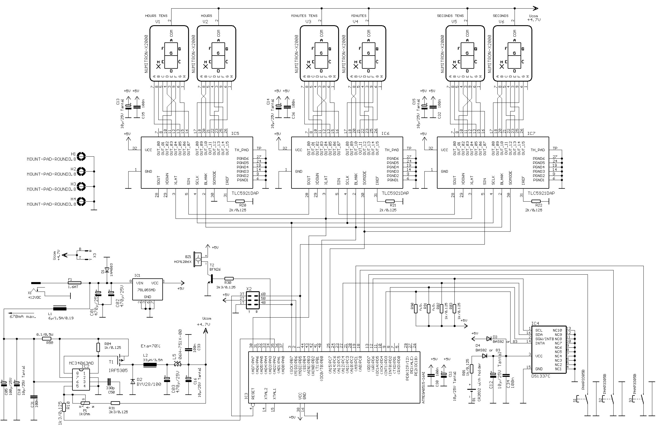
Numitrons are display devices similar to Nixie tubes, specifically designed for low voltage applications. They function as incandescent displays, utilizing filaments for the segments. A typical seven-segment readout comprises seven narrow illuminated bars arranged to create a rectangular figure...
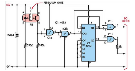
Here is how to build a pendulum-controlled clock that can be made very accurate. Retro? Yes, but it is an interesting project nonetheless. You will need a specific set of components. A pendulum-controlled clock is a mechanical timekeeping device that...
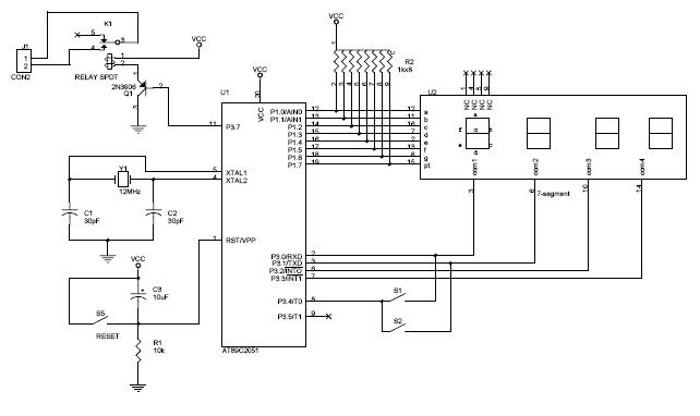
The circuit diagram above illustrates the Clock Controller V1.1. Pins P3.0 to P3.3 are connected to the base of a 4-PNP transistor, specifically the 2N2907, which is used to sink current. The Clock Controller V1.1 circuit is designed to manage...
Excellent clock generator to drive 4017 type cmos circuits. R1 = 10K to 10M, C1 = 100pF to 47uF. Fo is ±1Kz when R1=100K and C1=10nF. Input voltage can be from 5 to 15V. The described clock generator circuit is...
Upon purchasing the slave dial, it arrived without instructions, packaging, or additional details. The only visible markings, aside from decades of grime, were on the face (SMITH SECTRIC, ACELEC SYDNEY) and some markings on the bracket holding the mechanism...
A clock-controlled relay, also known as a time delay relay, allows for the automatic activation of a load, such as a water pump, at a predetermined time. This device utilizes a standard clock mechanism to trigger the circuit, enabling...