
Radio alarm clock

The circuit design incorporates a PIC16F874 microcontroller, which serves as the central processing unit for handling input from touch buttons and processing DCF time signals. The microcontroller's eight AD ports facilitate the connection of seven touch buttons and one LDR for light measurement. Each touch button is connected to an individual AD port, allowing for precise analog readings that correspond to user interactions.
The integration of the DCF module is crucial for time synchronization. The module outputs a digital signal, which is received by the microcontroller on pin 6. The connections are straightforward: the ground pin of the DCF module connects to the system ground, the power pin connects to a +5V supply, and the DCF-out pin provides the time signal to the microcontroller. This setup allows the software to interpret the DCF signal and adjust the internal clock of the PIC accordingly.
For the LCD backlight control, the LDR is placed in a voltage divider configuration with a fixed resistor, allowing the microcontroller to measure the voltage across the LDR. The PWM functionality of the PIC16F874 is employed to adjust the brightness of the LCD backlight based on the voltage reading from the LDR. This creates an adaptive lighting system that enhances visibility in varying ambient light conditions, improving user experience.
Overall, this design effectively combines touch sensing, timekeeping, and adaptive lighting into a cohesive system, leveraging the capabilities of the PIC16F874 microcontroller and external components to create a responsive and user-friendly interface.The program makes use of the built-in AD converter of the PIC16F874 for sensing the touch buttons. The PIC has 8 AD ports, seven are used for the 7 touch-buttons, 1 is used for the light measurement. In order to receive DCF signals, you have to add a DCF module (e. g. Conrad nr. 641138 - 89) which will provide a digital TTL level DCF signal which i s than interpreted by the software to automatically adjust the time. If you use the Conrad module, pin 1 of this module goes to ground, pin 2 to +5VDC and pin 3 (DCF-out) to pin 6 of the PIC. The backlight of the LCD can be dimmed either manually or automatically, proportional to the ambient light.
This is done using an LDR as a light sensor and the PWM capability of the microprocessor. 🔗 External reference
Related Circuits
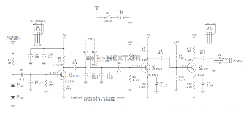
This version sports a 2nd audio amplifier stage at Q3. The output level with this version is sufficient to drive a crystal headphone to a comfortable volume. The "crystal" headphone is like those used on ye olde crystal radios....
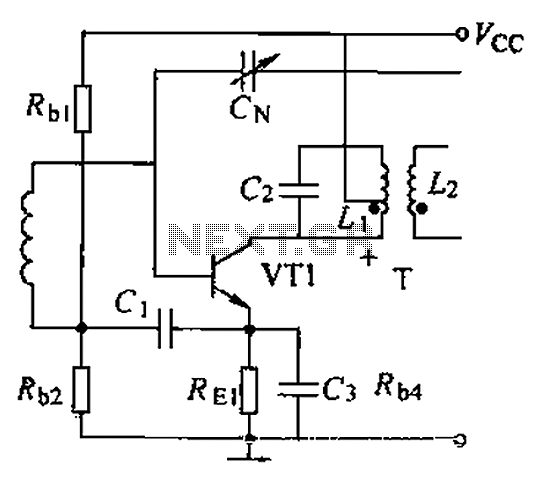
A common intermediate frequency amplifier circuit is presented, along with its components and parameters. The reference values for the components are as follows: 1) Transistors: VT1 to 3DG19, Vcc = 6V. 2) Resistance values: R1 = 50 kΩ, R2...
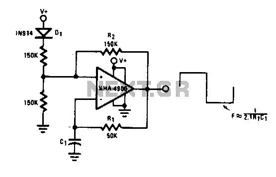
This self-starting fixed frequency oscillator circuit provides excellent frequency stability. R1 and C1 form the frequency-determining network, while R2 supplies regenerative feedback. Diode D1 improves stability by compensating for the difference between Voh and Vsupply. In applications requiring a...
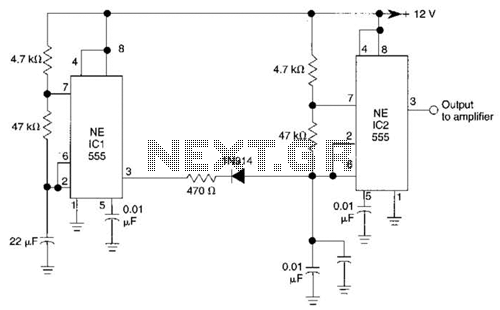
IC1 generates a pulse that modulates the 1000-Hz tone generated by IC2. This circuit can be used to generate warning or alert signals. The circuit described consists of two integrated circuits (ICs), where IC1 is responsible for generating a pulse...
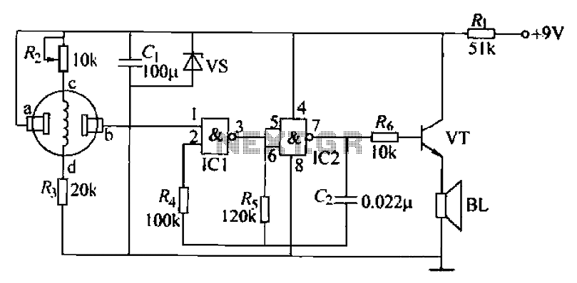
The combustible gas alarm circuit is depicted. The circuit comprises a gas sensor, a multivibrator, and audio output components. The multivibrator is implemented using two NAND gates within an integrated circuit (IC2) and includes external resistive and capacitive components....
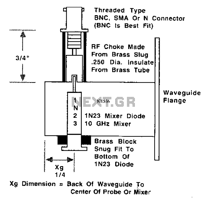
This is a 10 GHz frequency amateur radio waveguide detector. The 10 GHz amateur radio waveguide detector is designed to operate within the microwave frequency range, specifically targeting the 10 GHz band commonly used in various amateur radio applications. The...