
extended counter using cd4017

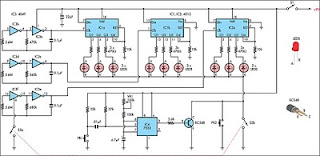
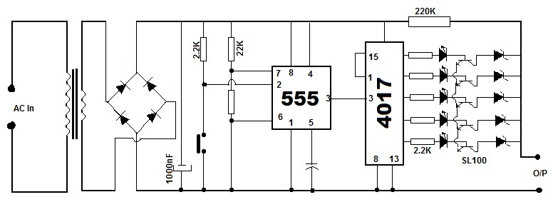
This circuit utilizes a 555 timer configured in astable mode to produce a continuous clock signal. The output from the 555 timer (IC1) is connected to a series of output pins (R0 to R8), which can be used to control various devices or components in the circuit. The initial grounding of pin 15 ensures that the circuit remains in a stable state until the button is pressed.
When the button (P) is activated, it creates a path for current to flow through resistors R1 and R2, which serves to limit the current to the base of transistor T1. This action turns on T1, allowing current to flow from the collector to the emitter, effectively energizing the relay coil. As the relay is activated, it can switch larger loads or control other circuits.
Additionally, the capacitor connected in the circuit plays a crucial role in timing and stabilization. It charges through the resistors, and once a certain voltage threshold is reached, it can influence the behavior of the circuit, such as providing a delay or smoothing out voltage fluctuations.
In summary, this simple yet effective circuit design demonstrates how a 555 timer can be employed to control a relay through a button press, utilizing basic components such as resistors, a transistor, and a capacitor to achieve desired functionality. Proper component selection and configuration are essential to ensure reliable operation and performance of the circuit.At the start condition all pin 15 are connected to the ground, so R0 is energized. A 555multivibrator sendsthe clock signalto IC1, which activates the outputs from R0 to R8. This simple circuit can be utilized to drive a monostable relay through a single button switch. At the start condition the relay does not work. When I press the button (P) T1 is energized through R1 and R2, and the capacitor charges. The coil is jumped by 🔗 External reference
Related Circuits
%2Bdecoder%2BCircuit%2Bschematic%2Busing%2BM8870.png)
This DTMF (Dual Tone Multi Frequency) decoder circuit identifies the dial tone from the telephone line and decodes the key pressed on the remote telephone. For the detection of DTMF signaling, the IC MT8870DE, a touch tone decoder IC,...
This circuit is a toy designed to encourage young children to count. Power is activated by switch S1, followed by closing switch S2, which causes nine LEDs to flash slowly. When S2 is opened, the LEDs turn off. Pressing...
For hobbyists or professional electronic engineers engaged in various electronic experiments, troubleshooting, or testing, it is essential to provide a wide range of variable options. In electronic engineering, the ability to manipulate and measure a wide range of variables is...
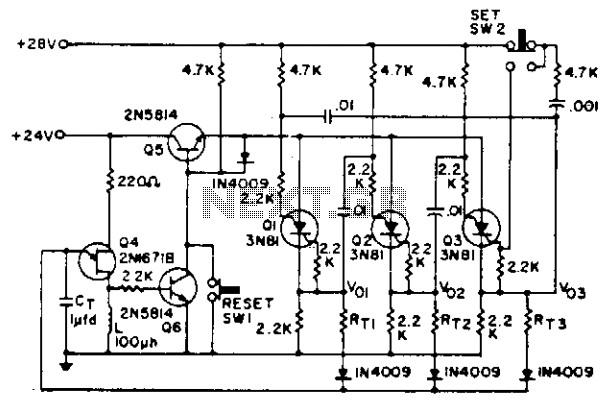
Shift pulses are generated by the unijunction transistors. The intervals between pulses are controlled by CT and RT. A different RT can be selected for each stage of the counter as shown. The circuit utilizes unijunction transistors (UJTs) to generate...
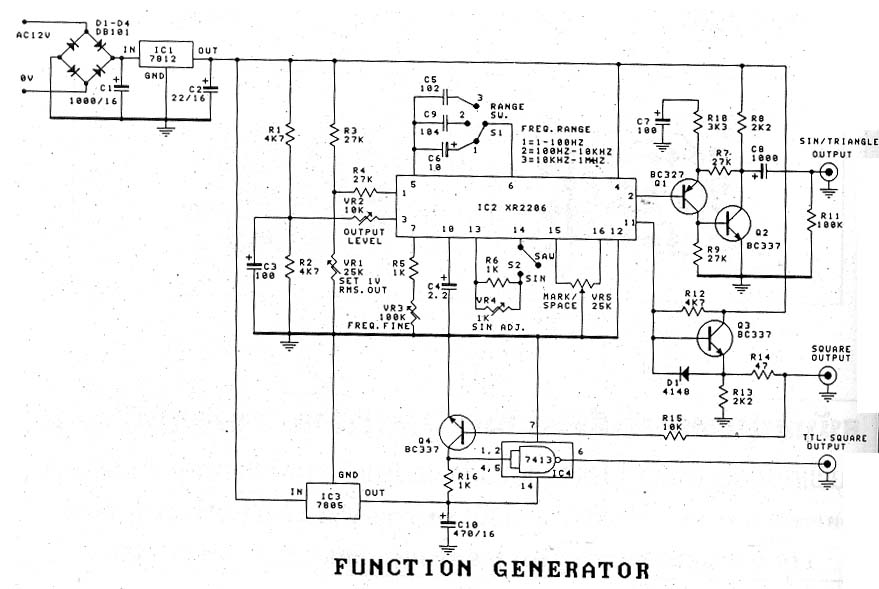
The signal generator, also known as "The Function Generator," is a device designed for use in a single machine. It is often associated with a significant cost. The function generator is a versatile electronic instrument used to generate various types...
Battery eliminators are circuits that create a DC power supply from AC mains. Essentially, battery eliminator circuits consist of a step-down transformer, rectifier, and voltage regulator. A simple circuit of a multipurpose battery eliminator features various output voltage ranges...