
Multipurpose Battery Eliminator Circuit using 4017 Decade Counter

Battery eliminators are essential for providing a stable DC voltage from an AC source, making them useful in various applications, including powering electronic devices that typically rely on batteries. The circuit begins with a step-down transformer that reduces the high AC voltage from the mains to a lower, manageable level. This lower AC voltage is then fed into a rectifier circuit, which converts AC to pulsating DC. The pulsating DC output is further smoothed using filtering capacitors to minimize voltage ripple, ensuring a more stable DC output.
The 555 timer IC, configured in monostable mode, generates a pulse signal that acts as a clock for the decade counter 4017. This counter effectively divides the pulse frequency to control the output voltage levels. Each output from the 4017 corresponds to a specific voltage level, which is selected by activating the appropriate transistor. The PNP transistors are configured to switch on and off based on the signals received from the decade counter. When a transistor is activated, it allows current to flow through a specific Zener diode, thereby regulating the output voltage to the desired level.
Zener diodes are critical components in this circuit, as they provide voltage regulation by maintaining a constant output voltage when reverse-biased. The selection of Zener diodes determines the output voltage levels available from the battery eliminator. This design allows users to obtain multiple output voltages, making the circuit versatile for various applications.
Overall, this multipurpose battery eliminator circuit efficiently converts AC mains power into a regulated DC output, offering flexibility in voltage selection while ensuring stable performance through the use of well-established electronic components.Battery Eliminators are the circuits, which creating DC power supply from AC Mains. Basically battery eliminator circuits are the compination of step down transformer, rectifier and voltage regulator. Here is a simple circuit of a Multipurpose Battery Eliminator, which has different range of out put voltages controlled by a decade counter 4017 ic
chip. First of all we need to convert AC to DC, which is doing by a Rectifier Circuit and we are creating a pulse generator using 555 timer IC wich is wired as Monostable mode After this the pulse is connecting to the decade counter 4017. Normally decade counter have ten out put shift register but here, in this circuit we are using only 5 out puts and 6th out is using to reset this shift register.
These out puts of the shift register are connected to the base of transistors, which is connected with voltage regulators (zener diods are used in this ciruit). In this circuit NE555 timer IC is wired as monostable miltivibrator and the third pin, out put pin of timer is connected to pin number 14 of 4017, which is the clock input.
Pin 3, 2, 4, 7 and 10 of 4017 is using outputs 1, 2, 3, 4 and 5 respectively. The sixth out put pin 1 is connected to the reset pin (15). Then the SL100, the PNP transistors are using to switch between diffrent voltages by diffrent voltage Zener Diodes. Each transistors will conncted while getting base voltage from 4017 and entire zener will be connected as voltage regulator.
🔗 External reference
Related Circuits
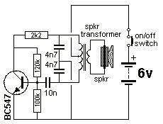
The Colpitts Oscillator is characterized by tapping the mid-point of the capacitive side of the oscillator section. The inductor can be the primary side of a speaker transformer. The feedback comes via the inductor. The Colpitts Oscillator is a type...
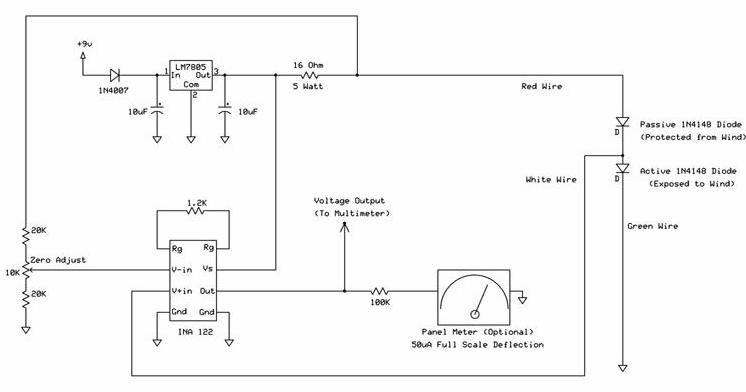
The following circuit illustrates a wind speed indicator circuit. It operates with a constant 5 VDC output provided by the LM7805 voltage regulator, using a 9 VDC supply. The wind speed indicator circuit is designed to measure and display wind...
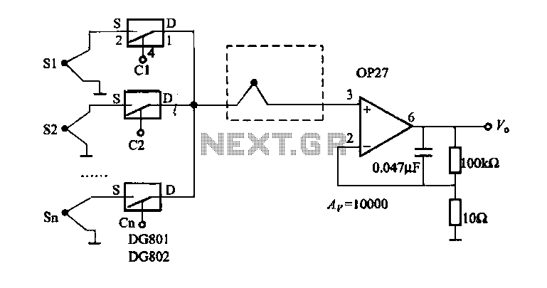
The electronic switch selection allows for multiple temperature control and monitoring points. It utilizes OP27 in conjunction with multiple S-type thermocouple circuits. The DG801/802 ultra-low on-resistance electronic switch has a maximum on-resistance of 0.40 ohms and operates under single-supply...
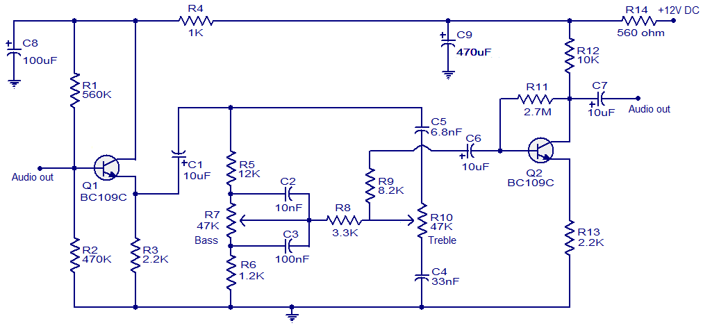
This simple tone control circuit is designed based on the renowned Baxendall tone control circuitry. The circuit can provide a maximum cut or boost of approximately 12 dB at both 10 kHz (treble) and 50 Hz (bass). Additionally, both...
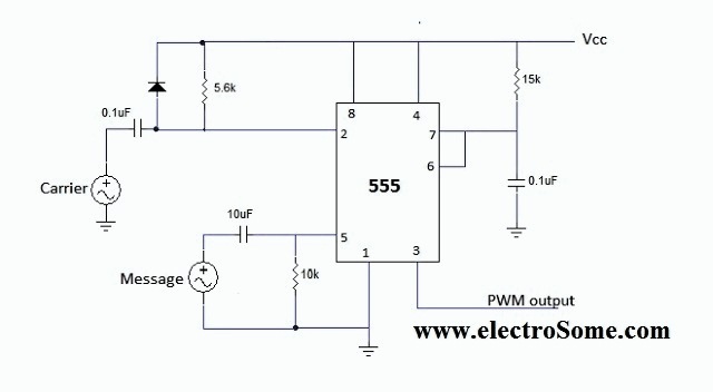
The 555 integrated circuit (IC) is configured in monostable mode of operation. In this mode, the output remains LOW (0V) when there is no trigger input. When a trigger is applied through pin 2, the output switches to HIGH...
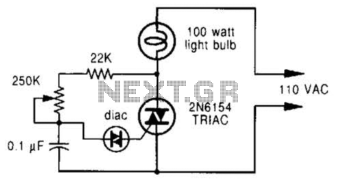
A phase-controlled dimmer delays the triac turn-on to a selected point in each successive AC half cycle. This circuit is suitable only for incandescent lamps, heaters, soldering irons, or universal motors that have brushes. A phase-controlled dimmer is an electronic...