
Extended On Time Timer Circuit

The described circuit leverages the capabilities of the Motorola MG14538B, a dual precision retriggerable monostable multivibrator, to produce a stable output pulse for a specified duration. By connecting a capacitor (C1) and a resistor (R1) to the timing input of the multivibrator, the time period during which the output remains high can be configured. The formula C1 * R1 = T is fundamental to determining the timing characteristics, where T represents the output pulse width in seconds.
In practical applications, this circuit serves as a switch debouncer, effectively filtering out noise caused by mechanical bouncing of switch contacts. When a mechanical switch is actuated, it does not transition cleanly from open to closed; instead, it may make and break contact several times before settling. This bouncing can lead to multiple unwanted triggers in digital circuits. By employing the monostable multivibrator configuration, the circuit ensures that only a single, clean transition is registered for each switch actuation, thus enhancing the reliability of digital inputs.
To implement this timer circuit, the selection of appropriate values for C1 and R1 is critical. For instance, using a capacitor value of 10 microfarads and a resistor value of 1 megohm would yield a time delay of approximately 10 seconds (10 µF * 1 MΩ = 10 seconds). This flexibility allows for customization based on the specific requirements of the application, whether it is for user interface controls, sensor triggers, or other digital input scenarios.
The MG14538B's dual functionality permits the use of both halves of the device in more complex applications, where multiple timing sequences or debouncing for several switches may be required. In summary, this circuit design is a robust solution for ensuring accurate digital signal processing in the presence of mechanical switch noise. Half of a Motorola MG14538B dual, precision, retriggerable mono stable multivibrator is used to form an extended on-time timer circuit. That type of circuit can be used as a switch debouncer. Such circuits are often used in digital circuitry, where each and every bounce of a switch contact is seen as a separate digital input.
The delay on time (established by CI and Rl) is easily set using the formula, C1 Rv = T, where Cj is in microfarads, R} is in megohms, and is in seconds.
Related Circuits
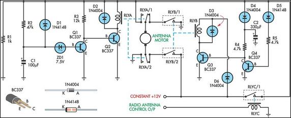
This up/down timer was designed to control a power antenna on a late-model vehicle. Normally, this vehicle uses a body computer to control the antenna. However, the owner intended to install a high-powered audio stereo system. The original stereo...
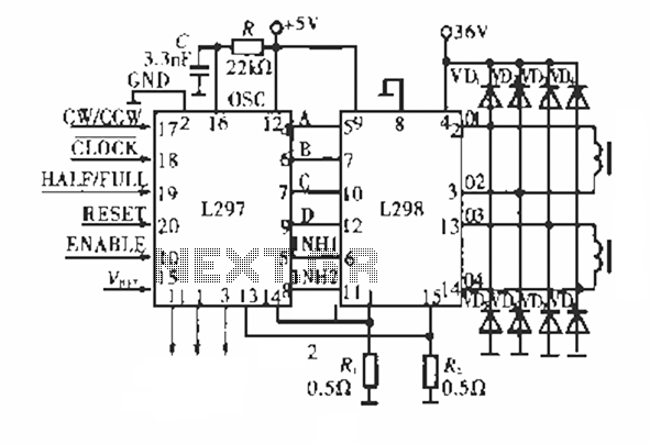
The circuit operates using a dedicated stepping motor controller, the L297. Pin 17 (CW/CCW) is utilized to control the rotation direction of the stepper motor. Pin 18 (CLOCK) regulates the speed of the stepper motor, while pin 19 (HALF/FULL)...
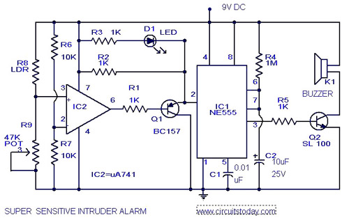
The circuit diagram illustrates an ultra-sensitive intruder alarm. The mere shadow of an intruder passing within a few meters of the circuit is sufficient to activate the alarm. In this setup, the IC2 uA741 is configured as a sensitive...
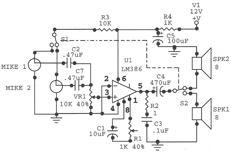
The LM386 is an ideal choice for a door phone application. This device is particularly beneficial in modern urban households, utilizing a condenser microphone and a speaker. The LM386 is a low-voltage audio power amplifier that is commonly used in...
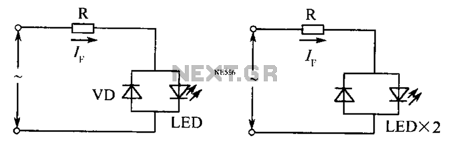
The circuit operates effectively even when the polarity of the voltage or the power supply is reversed. It functions with DC drives similar to AC drives, utilizing a current limiting resistor R. The value of this resistor is determined...
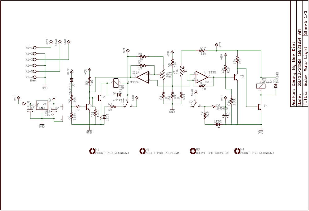
Few years back, I had been working on a project for solar auto lighting. The light will turn on when the solar panel voltage drop below a set point indicating that it is dark. The detection is done by...