
AC LED drive circuit

The described circuit is designed to accommodate both AC and DC power sources, ensuring reliable operation regardless of polarity. It incorporates a current limiting resistor, denoted as R, which plays a critical role in protecting the circuit from excessive current that could potentially damage components. The resistor's value is calculated in relation to the root mean square (RMS) voltage of the AC supply, which is essential for ensuring that the circuit operates within safe current limits.
In practical applications, the circuit can be employed in various devices where power supply polarity may be uncertain. This feature is particularly advantageous in environments where power connections may be made incorrectly, as it mitigates the risk of damage to sensitive electronic components. The design may also include additional protective elements such as diodes to prevent reverse polarity damage and to ensure that the circuit remains functional under varying conditions.
When designing the current limiting resistor, it is important to consider the maximum expected RMS voltage and the desired current limit for the application. The resistor value can be calculated using Ohm's law, where the resistance R is equal to the voltage (V) divided by the current (I). This relationship ensures that the circuit operates efficiently and safely, maintaining the integrity of both the power supply and the connected loads.
Overall, the circuit's ability to handle reversed polarity and its adaptability to both AC and DC drives make it a versatile solution in electronic design, suitable for a wide range of applications. As shown, still work in the case of unknown polarity of the voltage or the power supply polarity is reversed. And DC Drives as AC drives, the current limiting resistor R whose value is: where, AC RMS voltage.
Related Circuits

This circuit is designed to convert continuously lit lamps into flashing lights. It can be easily integrated into an existing circuit by inserting it between the lamp and the negative supply. It is particularly suitable for use with car...
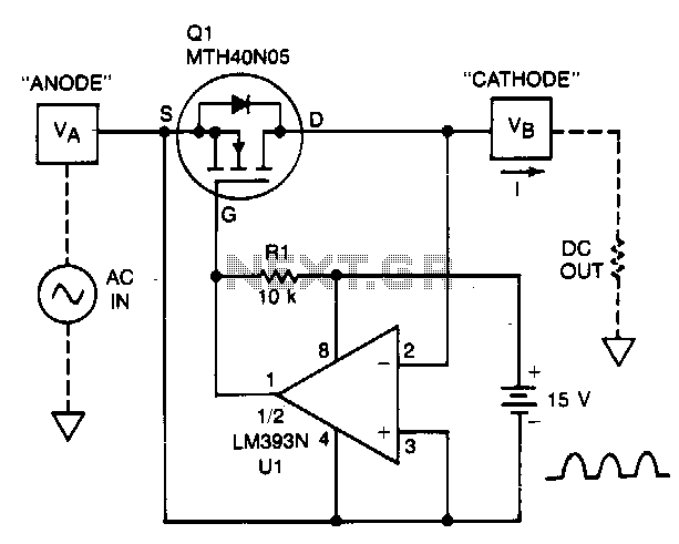
A TMOS power FET, Q1, and an LM393 comparator provide a high-efficiency rectifier circuit. When voltage V1 exceeds V2, the output of U1 becomes high, and Q1 conducts. Conversely, when V2 exceeds V1, the comparator output becomes low, and...
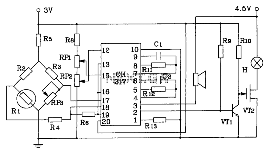
CH217 is a monolithic gas detection alarm integrated circuit. The gas detection alarm circuit diagram includes R1 as the gas sensing probe, where the resistance increases as the gas concentration decreases linearly. RP3 is used to adjust the output...
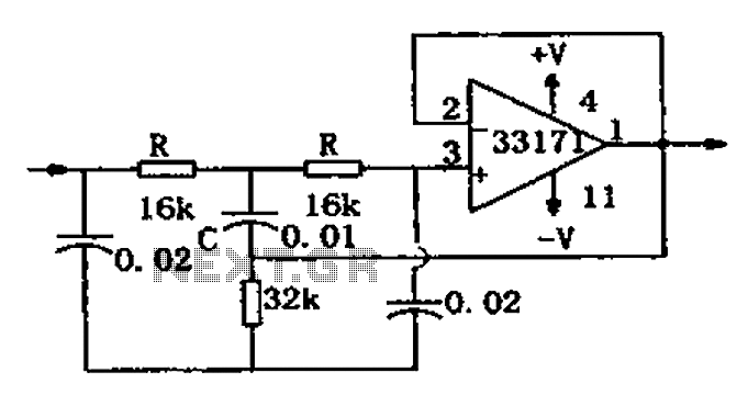
The trap circuit utilizes a high-performance operational amplifier, MC33171, to create the trap. This device features a wide bandwidth and high conversion rate. The component values can be modified by adjusting the capacitance of capacitor C and the resistance...
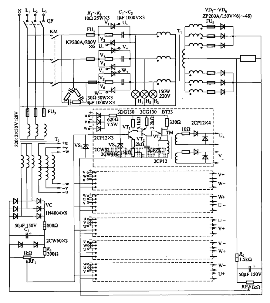
A three-phase thyristor power regulator circuit designed for plating applications, capable of handling currents from 1200A to 6000A at a voltage of 10V. The circuit comprises a main circuit, a trigger circuit, synchronous power components, and a voltage negative...
Just to prove that transistors can also be useful in logic situations; this is a data latch and indicator which also is a data switch and has a bidirectional input/output port which can be read or switched. If the...