
eZdsp F2812 Tutorial

Soldering Connectors: Since the analog-to-digital converter (ADC) and the serial peripheral interface (SPI) on the eZdsp S kit will be used, two connectors need to be soldered onto the board. One header should be soldered onto pins 20-26 on the outline labeled P8, which deals specifically with SPI signals. The second header should be soldered onto pins 2, 4, 6, 8, 10, 12, and 14 on the outline labeled P9, where the analog signals are located. TI's multi-converter evaluation module (EVM) is a kit that allows users to evaluate the performance of several devices in the multipurpose (MP) family of data converters. It is designed to work with the TMS320 DSPs and comes with six different ADCs and ten various DACs. For this lab, the TLV5638 dual 12-bit DAC will be used.
Setting up the EVM: The EVM has a header labeled J11 that must be connected to header P8 on the eZdsp board. Using wires, connect the relevant headers. Once the boards are connected, the next step is to power up the EVM board. The EVM operates on four voltages: -12V, 0V, 12V, and 5V. Solder one wire to each pin in connector J7. After partially stripping each wire, use a power supply source to deliver the proper voltage to each pin. The D1 LED should light green when done correctly. Since a DSP will be used to generate signals, the EVM board must be configured accordingly. Ensure that the SW1 switch on the right side of the board is set correctly.
Another option for using an external DAC is the audio processing daughtercard, which was designed after the eZdsp was successfully set up to communicate with the TLV5638 DAC on the EVM. The only preparation required for the eZdsp to interface with the audio processing daughtercard is to solder two headers to P8 and P9. After mounting the audio processing board on the eZdsp F2812, connect the power supply and parallel cable to the eZdsp. The LED labeled 'Power' on the daughtercard should light up bright orange if done correctly. Additionally, connect the provided speaker to the jumper labeled 'R_SPKR' on the daughtercard, ensuring the black wire is connected to the '-' and the red wire is connected to the '+'.
For this lab, an Apple iPod will be used to supply the audio source, which must be connected with the supplied cable to the jumper labeled 'J4' on the daughtercard. Since the iPod does not have a reliable battery, it should be connected to a power supply. The setup should be organized accordingly.
Controls: The daughtercard features two potentiometers that will be programmed later in this lab to control the volume of the output signal and the spectrum of filters that will be applied to the input signal. In this part of the lab, Code Composer Studio will be used to implement the software for the FIR filter on the audio signal. For those unfamiliar with Code Composer Studio, reviewing the ELEC 424 tutorial before beginning is recommended. Several peripherals and interfaces will be utilized, and background information will be provided for each. For further information, refer to the References section at the end of this lab manual. The serial peripheral interface (SPI) is a high-speed communication protocol utilized in this setup.
This comprehensive setup involves careful soldering of connectors, proper voltage supply connections, and the integration of both the audio processing daughtercard and the EVM to facilitate the implementation of the FIR filter. The use of Code Composer Studio for programming ensures that the DSP can effectively process audio signals, allowing for real-time audio filtering and manipulation.The purpose of this lab is to learn how to prepare Spectrum Digital`s eZdsp F2812 to implement a finite impulse response (FIR) filter using an audio input. Since the F2812 does not have a digital-to-analog converter (DAC) as one of its peripherals, this lab will cover setting up the eZdsp to use two options: The eZdsp F2812 allows people
to determine if the TI TMS320F2812 digital signal processor (DSP) is suitable for their application requirements. It also allows evaluators to develop and run software for the F2812 processor by using Code Composer Studio.
A separate tutorial for the Code Composer Studio software will be available in this course. To begin this lab, there are several tasks you will have to accomplish in order to set up your hardware before programming the DSP. Some background information has been provided, but if you like additional information, please refer to the References section at the end of this lab.
The eZdsp requires a 5V power supply that is provided and should be connected to the board via connector P6. The supplied parallel cable also needs to be plugged into a PC that has Code Composer Studio installed on it.
Soldering Connectors Since we will be working with the analog-to-digital converter (ADC) and the serial peripheral interface (SPI) on the eZdsp S kit, we will want to solder two connectors on the board. One header should be soldered onto pins 20-26 on the outline labeled P8 which deals specifically with SPI signals.
The second header should be soldered onto pins 2, 4, 6, 8, 10, 12, and 14 on the outline labeled P9 which is where the analog signals are located. TI`s multi-converter evaluation module (EVM) is a kit that allows users to evaluate the performance of several devices in the multipurpose (MP) family of data converters.
It is designed to work with the TMS320 DSPs. It comes with six different ADCs and ten various DACs. For the purpose of our lab, we will be using the TLV5638 dual 12-bit DAC. Setting up the EVM The EVM has a header labeled J11 that needs to be connected to header P8 on the eZdsp board. Using wires to do so, connect the following: Once the boards are connected, powering up the EVM board is the next step.
The EVM operates on four voltages: -12V, 0V, 12V, and 5V. Solder one wire to each pin in connector J7. After partially stripping each wire, use a power supply source to deliver the proper voltage to each pin. The D1 LED should light green when done correctly as shown in the following picture: Since we will be using a DSP to generate signals, we will want to make sure the EVM board is configured as such.
Look for the SW1 switch on the right side of the board and make sure the following is set: Another option for using an external DAC is the audio processing daughtercard that was designed after the eZdsp was successfully set up to communicate to the TLV5638 DAC on the EVM. In this section, we will show how to set up the eZdsp to communicate with the daughtercard. Soldering The only preparation the eZdsp requires to interface with the audio processing daughtercard is to solder two headers to P8 and P9 to the eZdsp : When you have the audio processing board mounted on the eZdsp F2812, then you will have to connect the power supply and parallel cable to the eZdsp.
The LED labeled Power` on the daughtercard should light up bright orange if done correctly. You will also have to connect the provided speaker to the jumper labeled R_SPKR` on the daughtercard. Make sure the black wire is connected to the - and the red wire is connected to the +`. For our lab, you will be using an Apple iPod to supply the audio source and that will have to be connected with the supplied cable to the jumper labeled J4 on the daughtercard.
Since the iPod we are using does not have a very reliable battery, be sure to have the iPod connected to a power supply. Your setup should look like this: Controls The daughtercard features two potentiometers that will be programmed later in this lab to control the volume of the output signal and the spectrum of filters that will be applied to the input signal.
In this part of the lab, we will be using Code Composer Studio to set up the software implementation of the FIR filter on an audio signal. If you are not familiar with Code Composer Studio, you might want to read over the ELEC 424 tutorial before you begin.
There are several peripherals and interfaces we will work with and a little background information will be given for each, but if you would like more information, please look under the References section at the end of this lab manual. The serial peripheral interface (SPI) is a high-speed . 🔗 External reference
Related Circuits
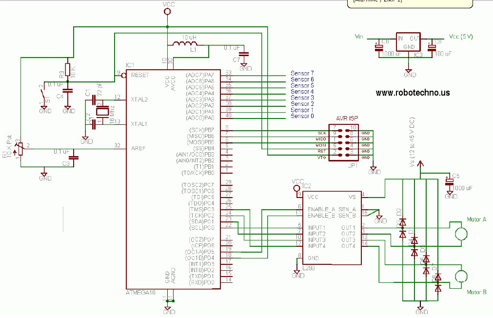
This line follower robot utilizes the following components: eight phototransistor proximity sensors, an ATMega16 microcontroller, an L298 motor driver, and is programmed using the C programming language. The line follower robot is designed to navigate along a designated path by...
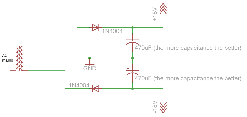
Afroman explains the fundamentals of transformer operation, where to purchase step-down mains transformers, and how to safely wire one to mains voltages. The discussion includes both European and North American wiring standards. The presentation concludes with a brief example...
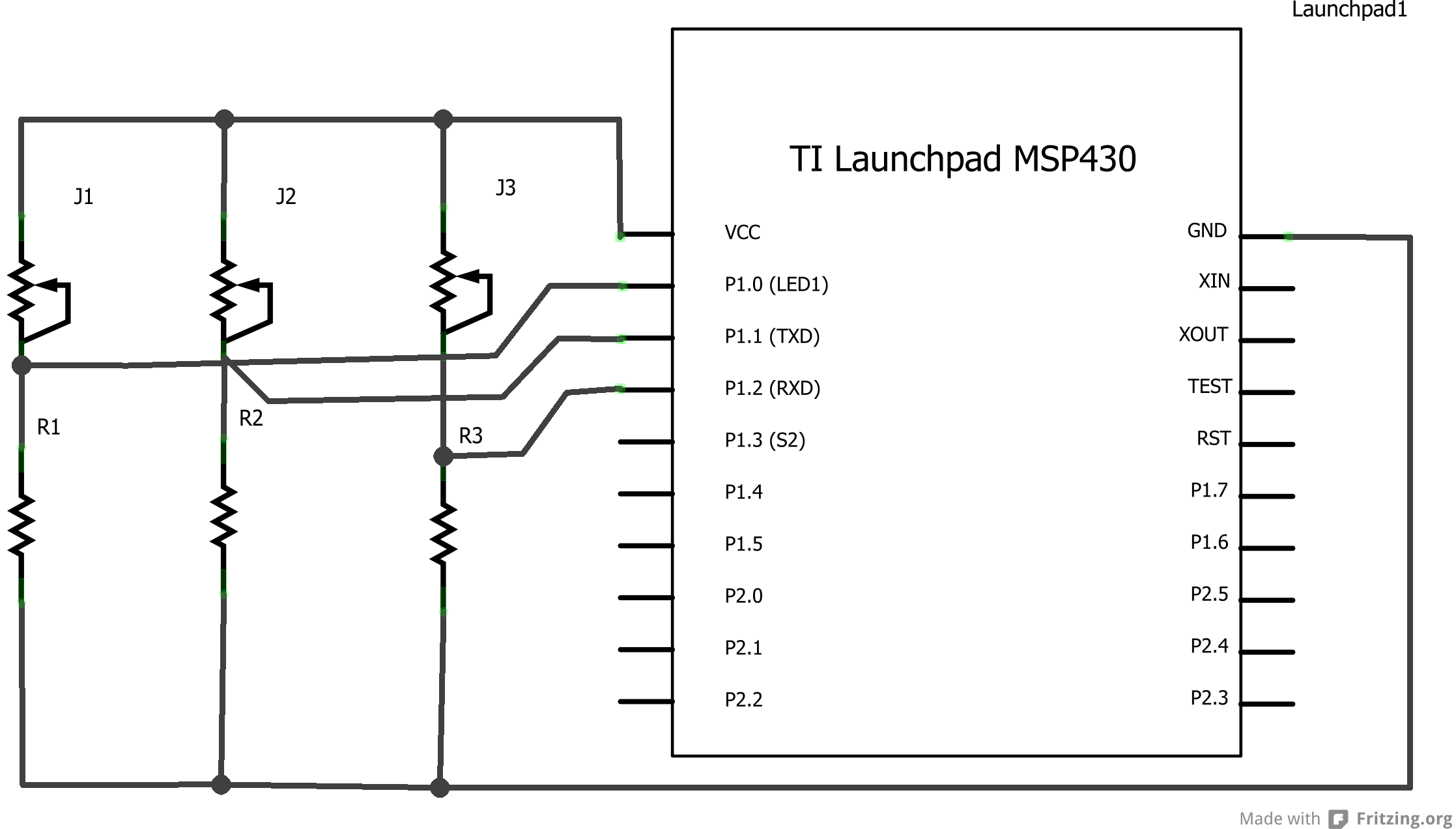
Energia is a rapid prototyping platform designed for the Texas Instruments MCU Launchpad. It is built on the principles of Wiring and Arduino and utilizes the Processing IDE. Energia offers an accessible environment for developing applications with Texas Instruments microcontrollers. By...
The bipolar junction transistor is one of the cornerstones of modern solid-state electronics. Understanding the basics of this important active device is essential. The Bipolar Junction Transistor (BJT) initiated the revolution in solid-state electronics during the 1960s. Although discrete...

Current sensing involves detecting the amount of current being used by a specific circuit or device. It is particularly useful for assessing the power consumption of various components within a robotic system. Although not commonly required in robotics, current...
This page outlines how to create a simple theft deterrent that can be quite effective. The concept involves using a flashing red LED to indicate that the vehicle is protected. This device serves to safeguard the car from potential...