
F M MODULATOR

The described circuit operates by applying a modulation signal to the base of an oscillator transistor, which is a critical component in generating frequency-modulated signals. The circuit is designed to achieve a frequency deviation of at least 200 kHz, which indicates the range of frequency variation from the carrier frequency that can be achieved without introducing significant distortion to the output signal.
The feedback mechanism incorporated into the circuit plays a vital role in maintaining a low output impedance. Low output impedance is essential for ensuring that the oscillator can drive subsequent stages of the circuit without significant signal loss or distortion. This characteristic enhances the overall performance of the telemeter transmitter by ensuring that the signal remains stable and reliable.
In practical applications, this type of circuit is commonly used in telemetering systems where accurate and stable signal transmission is required over varying distances and conditions. The ability to modulate the frequency effectively while minimizing distortion is crucial for maintaining the integrity of the transmitted data.
The oscillator transistor's configuration, along with the feedback network, should be carefully designed to optimize performance parameters such as bandwidth, linearity, and power efficiency. Components such as resistors, capacitors, and inductors may be utilized to fine-tune the circuit's response and ensure that it meets the desired specifications for telemetering applications.
Overall, the design principles outlined provide a robust framework for developing advanced telemeter transmitters that leverage transistor technology for efficient signal modulation and transmission.Provides at leaet 200 kc deviation when applied to base of oscillator transistor, before severe distortion sets in. feedback keeps output impedance low. -D. Enemark, Transistors Improve Telemeter Transmitter, Electronics, 32:11, p 136-137. 🔗 External reference
Related Circuits
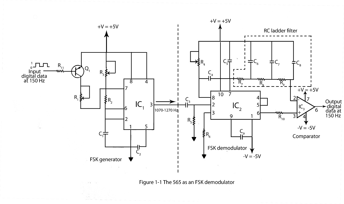
The frequency shifting keying technique is utilized to transmit binary data. The circuit diagram includes a description of an FSK demodulator that employs the 565 integrated circuit for frequency shift keying. The frequency shift keying (FSK) technique is a form...
The first example utilizes a standard op-amp oscillator circuit to produce a triangular waveform, which is then level-shifted and supplied to a comparator (e.g., LM339) to generate a PWM waveform. It is common for users to prefer using two...

If one has considered experimenting with pulse-width modulation, this circuit serves as an excellent starting point. The design prioritizes simplicity by utilizing a dual 555 timer, making the assembly straightforward. A small PCB has been created for this purpose,...
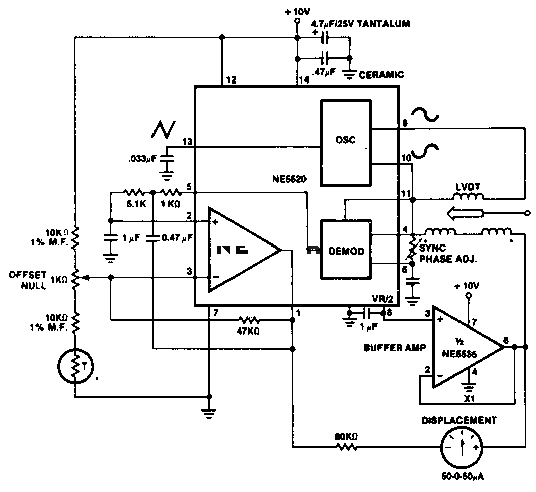
A simple motion transducer can be constructed using the provided circuit. The output is biased to one-half of the supply voltage, necessitating special interface circuitry for signal readout. One straightforward method involves utilizing a zero-center meter in a bridge...

A simple single sideband (SSB) suppressed carrier demodulator circuit can be constructed using the LM1596 balanced modulator-demodulator integrated circuit (IC). The carrier signal should be applied to the carrier input port at an optimal level of 300 mVrms to...
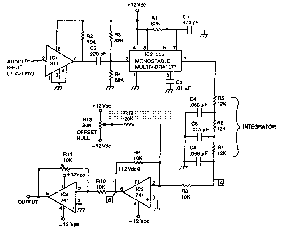
The circuit recovers an FM audio signal that varies from less than 1 kHz to about 10 kHz. The circuit is designed to demodulate frequency-modulated (FM) audio signals within the frequency range of less than 1 kHz to approximately 10...