
Telemetry demodulator

The circuit is designed to demodulate frequency-modulated (FM) audio signals within the frequency range of less than 1 kHz to approximately 10 kHz. The primary function of this circuit is to extract the original audio information from the modulated carrier wave, allowing for playback or further processing of the audio signal.
To achieve this, the circuit typically includes several key components: an antenna for receiving the FM signal, a radio frequency (RF) amplifier to boost the signal strength, and a demodulator stage that converts the FM signal back into an audio frequency (AF) signal. The demodulation process often employs a phase-locked loop (PLL) or a discriminator circuit, which can effectively track the variations in frequency of the incoming FM signal.
After demodulation, the audio signal may undergo additional processing, such as filtering to remove any residual RF components and amplification to bring the signal to a suitable level for output. The final output stage may include a low-pass filter to ensure that only the desired audio frequencies are passed through, effectively eliminating any high-frequency noise that may have been introduced during the transmission.
The circuit's design must also consider factors such as signal-to-noise ratio (SNR), distortion, and the overall bandwidth to ensure high-quality audio reproduction. Proper layout and component selection are critical to minimize interference and maintain signal integrity throughout the circuit.The circuit recovers an FM audio signal that variesfrom less than 1 kHz to about 10 kHz.
Related Circuits

This is a circuit design for an FSK demodulator, which is an electronic device that converts an FSK signal into a serial digital signal. FSK modulation is used to transmit digital serial data, and demodulation is necessary to retrieve...
The Pulse Demodulator, as illustrated in the accompanying image, consists of a CMOS Hex Inverter. This circuit is capable of performing envelope detection on amplitude pulses. The Pulse Demodulator utilizing a CMOS Hex Inverter is designed to extract the envelope...
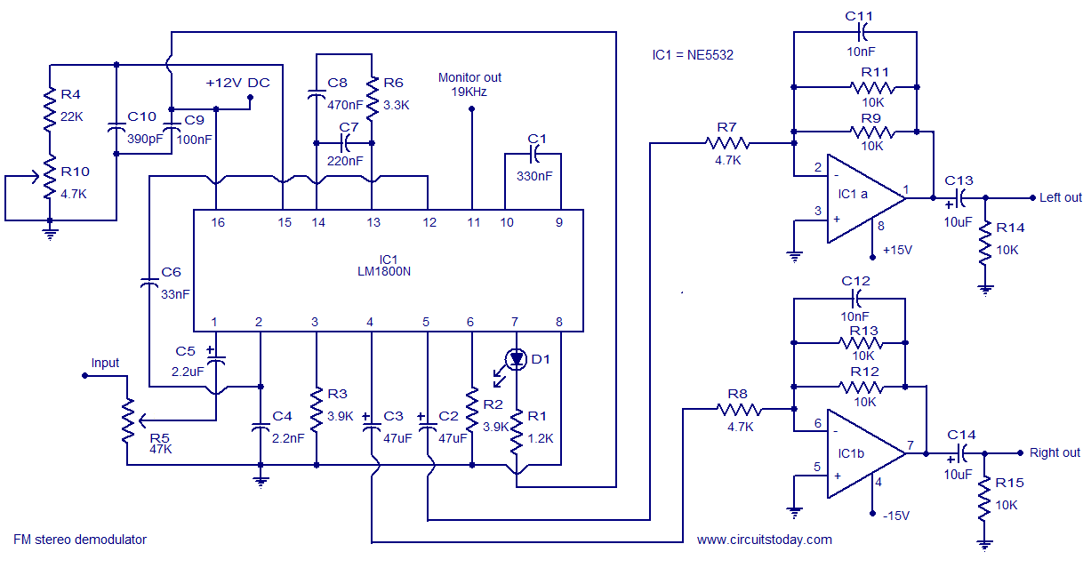
The following circuit illustrates the LM1800 IC Integrated FM Stereo Demodulator Circuit. Features include excellent sound quality and high-quality FM stereo. The LM1800 Integrated Circuit (IC) serves as a highly effective FM stereo demodulator, designed to deliver superior audio performance...
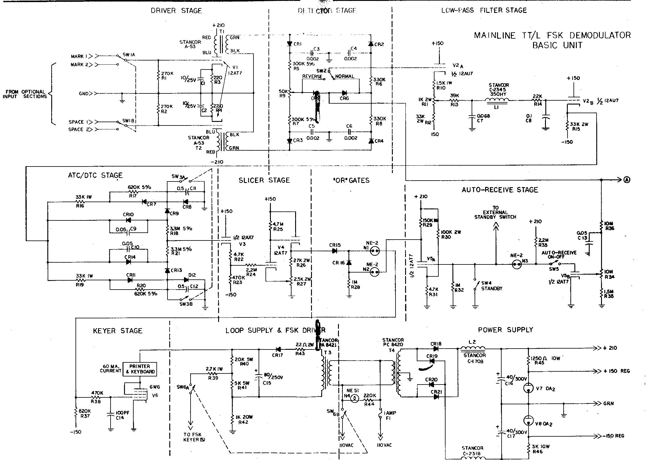
The term "demodulator" is becoming a standard in both commercial and military sectors. "Converters" are often associated with devices that automatically transform Morse code into RTTY, convert 8-level signals to 5-level, or adjust baud rates from 50 to 45,...
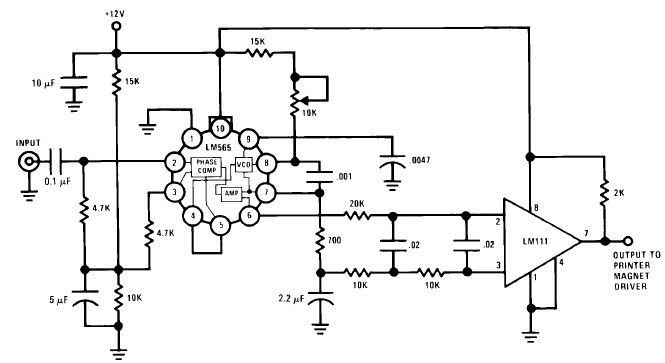
A simple Frequency Shift Keying (FSK) demodulator for 2025 Hz and 2225 Hz can be designed using the LM565, a general-purpose phase-locked loop integrated circuit. This IC includes a stable, highly linear voltage-controlled oscillator that provides low distortion FM...
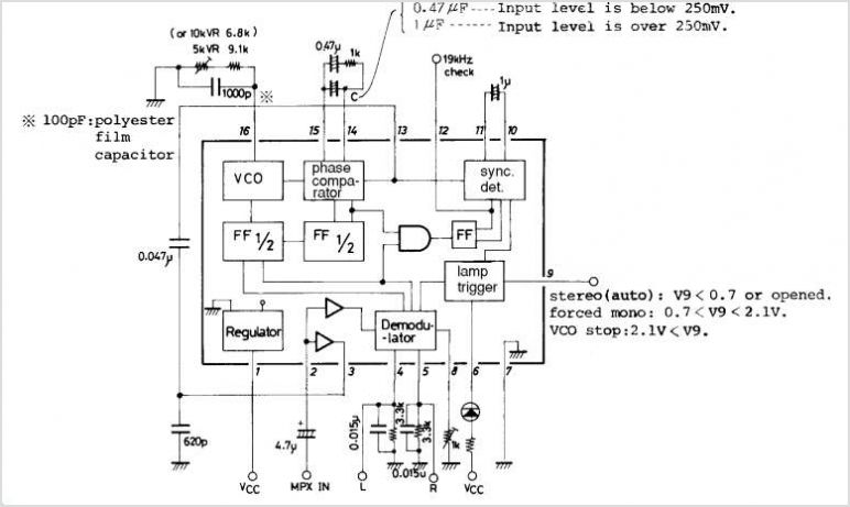
The LA3370 is a multiplex integrated circuit (IC) designed for FM car stereo applications. It performs two primary functions using the intermediate frequency (IF) meter output voltage: 1. Stereo Noise Control (SNC), which effectively reduces noise specific to FM...