
F/V Converter in CLosed Loop Motor Speed Control System

A closed-loop control system, commonly referred to as a servo system, is designed to maintain a desired output by continuously monitoring and adjusting the input based on feedback from the system. This type of system is essential in applications where precise control is required, such as in robotics, industrial automation, and aerospace engineering.
In a typical closed-loop system, the key components include a controller, a sensor, an actuator, and the plant itself. The controller processes the error signal, which is the difference between the desired setpoint and the actual output measured by the sensor. The controller then generates a control signal that is sent to the actuator, which modifies the input to the plant to achieve the desired output.
The plant represents the process or system being controlled, which can include mechanical, electrical, thermal, or fluid systems. The stability of the closed-loop system is crucial; it ensures that the output remains within the desired range even in the presence of disturbances or changes in system dynamics.
Feedback mechanisms play a vital role in maintaining system stability. Positive feedback can lead to instability, while negative feedback is employed to reduce the error signal and stabilize the system. Various control strategies, such as proportional-integral-derivative (PID) control, are often implemented to enhance the performance of closed-loop systems by optimizing the response time and minimizing overshoot.
Overall, closed-loop systems are fundamental in modern engineering, enabling precise control and automation across a wide range of applications.Closed loop or servo system has the ability to stabilize the controlled plant at a specified operating condition. The plant, the controlled sub-system, can be.. 🔗 External reference
Related Circuits
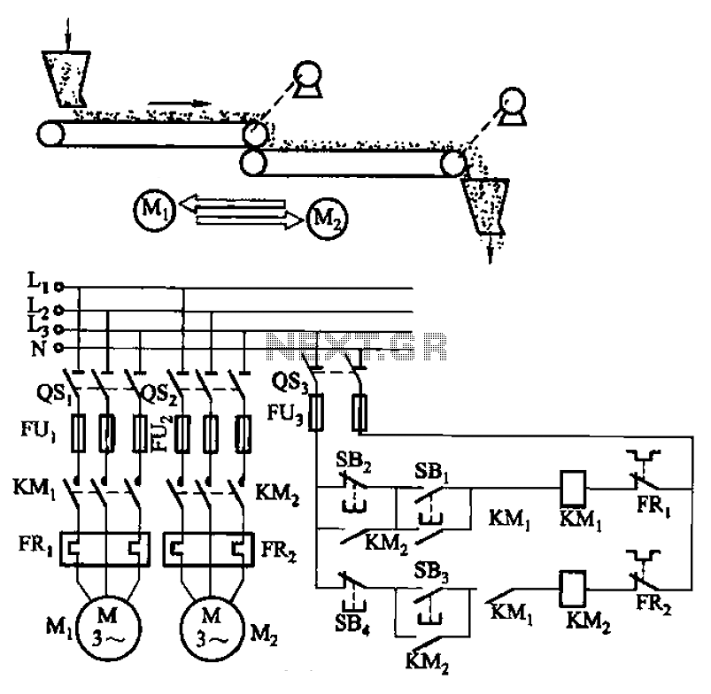
The circuit depicted in Figure 3-86 utilizes a line utilization time relay to control two motors, starting one before the other after an initial stall. The time relay KTi can be adjusted to modify the starting interval of the...
Two detector systems in the Hall-A spectrometers utilize potentially flammable gases: the Vertical Drift Chambers (VDC) and the Focal Plane Polarimeter (FPP) straw tubes. This document aims to provide a user manual for the gas supply system and fulfill...
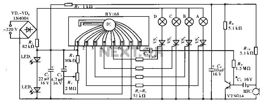
The circuit operates with a controller that includes a power supply circuit, a control circuit, and an audio amplifier, which are three distinct components. The power circuit comprises diodes VD1 to VD4, resistor R1, capacitor C1, LED1, LED2, and...
The simplest solution for implementing joystick control for a robot is to program the actions in software on a microcontroller. However, many users prefer off-the-shelf components, thus this circuit is designed using diodes, resistors, transistors, and a FAN8200 motor...
This circuit is designed to create an early warning alarm system for any form of theft that is important to the owners of a motorcycle or bicycle. This alarm system can utilize a number of normally open switches, such...
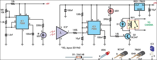
The IR detector (IC3) controls an LM 7555 CMOS timer (IC2) operating in monostable mode. When the beam is interrupted, IC2 is triggered, causing its pin 3 output to go high for approximately half a second. This action turns...