
Lighting controller circuit

The circuit is designed to efficiently convert high-voltage AC into a usable DC format for various applications. The power supply section utilizes a full-wave bridge rectifier composed of diodes VD1 through VD4. This arrangement allows for the conversion of the alternating current (AC) input into direct current (DC) by allowing current to flow in a single direction, effectively smoothing the output waveform.
The output from the rectifier is a pulsed DC signal, characterized by its fluctuating voltage levels. To ensure that this output is suitable for driving the four bulbs (A, B, C, D), the circuit employs a Buck converter configuration. This step-down converter is essential for reducing the voltage level to a safe and functional range, which is particularly important for LED operation.
The inclusion of resistors and capacitors, such as R1 and C1, plays a critical role in filtering the rectified output and stabilizing the voltage. Capacitor C1 works to smooth out the ripples in the pulsed DC output, providing a more consistent voltage level to the load. The resistive element R1 may also be used to limit current and protect the circuit components from excessive current flow.
LED1 and LED2 serve as indicators within the circuit, providing visual feedback on the operational status. The illumination of these LEDs signifies that the circuit is functioning correctly and that power is being supplied to the connected bulbs. The overall design of this circuit ensures reliability and efficiency in converting and regulating electrical power for various lighting applications.Circuit works: The controller consists of a power supply circuit, a control circuit and audio amplifier is composed of three parts. Power circuit from the VD1 ~ VD4, R1,, C1, LED1 and LED2 and other components. After 220 V AC by VD1 VD4 a full-wave bridge rectifier output pulse red DC for four bulbs A, B, C, D use. This pulsed DC has been brother Buck limiting make LED1, LED2 light.
Related Circuits
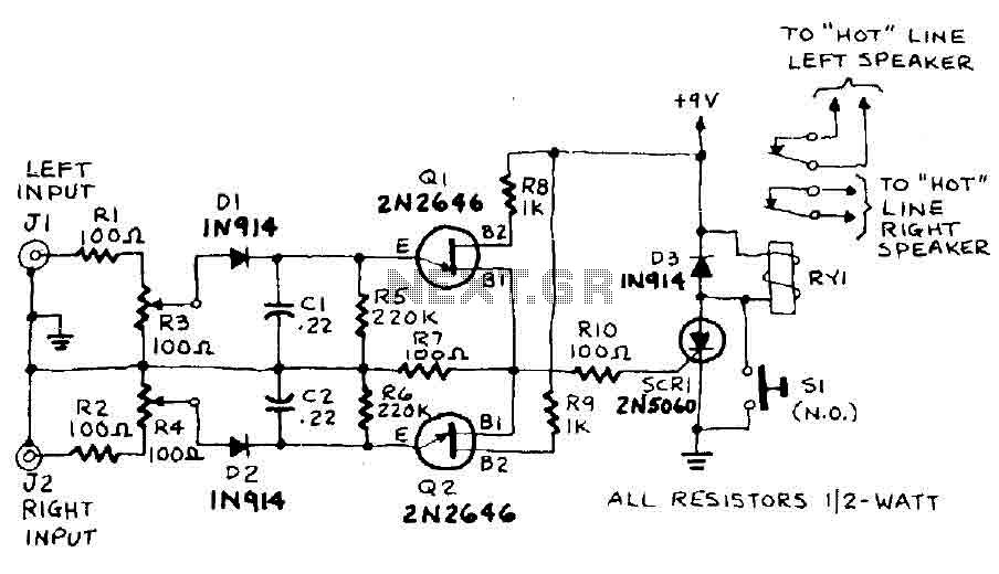
The circuit input is derived from the terminal loudspeaker or amplifier output jacks. If the right channel signal is sufficiently strong to charge capacitor C1 to a potential that exceeds the breakdown voltage of the emitter of transistor Q1,...
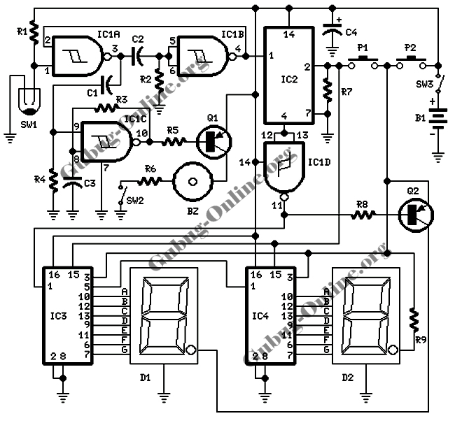
This design features a signal logic tester that utilizes a common cathode seven-segment display. The display indicates a logic level "1" (represented by an "H" on the display) or a logic level "0" (represented by an "L" on the...
The metal detector circuit comprises an oscillator and a sound-light alarm circuit. The oscillator circuit includes an inductor (L), a capacitor (C1), a sensor switch integrated circuit (IC1) that integrates the oscillator, detector, comparator circuit, and peripheral components. The...
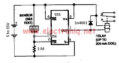
The water sensor circuit utilizes a 555 timer circuit along with common electronic components. It consists of two metal electrodes positioned closely enough that a drop of water can create a conductive bridge between them. If the water is...
This page will be updated as material becomes available. This new system will essentially replace the original BCD design, which was created by WB6IGP and N6IZW and was featured in the ARRL UHF/Microwave Project Manual. Their work was later...
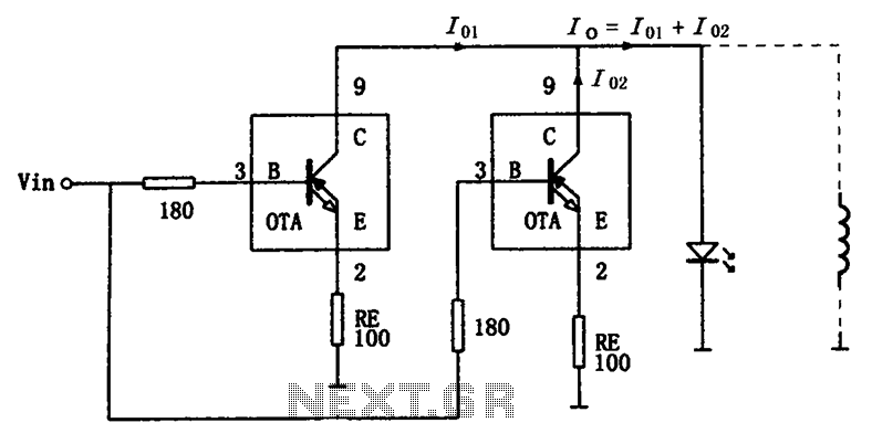
The high-speed parallel current drive circuit utilizes the OPA660 operational transconductance amplifier (OTA). An input signal, Vin, is connected to a 180-ohm resistor equivalent device at the base (pin 3) of the OPA660. The collector (pin 8) is directly...