
Factory Alarm

The circuit employs a capacitor connected to pin 5 of the IC, which plays a crucial role in frequency modulation. Initially, upon powering the circuit, the capacitor begins to charge through a resistor, leading to a gradual increase in voltage at pin 5. This voltage change affects the oscillation frequency of the IC, causing it to rise steadily. The time constant of the charging process, determined by the values of the capacitor and resistor, dictates how quickly the frequency ramps up.
Once the capacitor reaches its maximum charge, the voltage stabilizes, and the frequency remains constant. This stable frequency can be utilized for various applications, such as generating a consistent tone for alarms or sirens.
The circuit also incorporates a push button switch that, when pressed, allows the capacitor to discharge. This discharge is facilitated through a discharge path that may include resistive elements to control the rate of discharge. As the capacitor discharges, the voltage at pin 5 decreases, leading to a reduction in frequency. The design ensures that the frequency modulation is responsive to user input, allowing for dynamic control of the siren's sound.
Overall, this configuration provides a simple yet effective method for frequency control in electronic circuits, particularly for alarm systems where variable sound output is desirable. The interaction between the capacitor's charge state and the IC's frequency output demonstrates fundamental principles of electronic timing and control.The frequency is controlled by the pin 5 of the IC. When the supply is switched ON, the capacitor charges slowly and this alters the voltage at pin 5 of the IC hence the frequenct gradually increases. After the capacitor is fully charged, the frequency no longer increases. Now when the push button siren control switch is held depressed, the capaci tor discharges and the siren frequency also decreases. 🔗 External reference
Related Circuits
The project was originally intended as a present for my brothers dorm room, but a bad capacitor and the lack of a proper oscilloscope caused delays. It has not made it off the breadboard, and it probably will not...
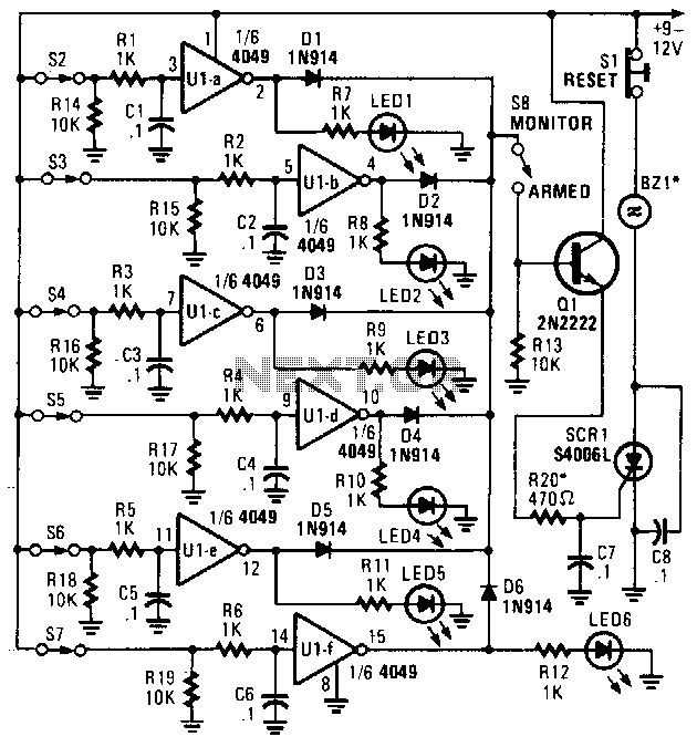
This alarm features status LEDs connected to each inverter output, which indicate the status of the corresponding sensor. S8 is utilized to monitor the switches through the LEDs or to activate an alarm using Q1 and SCR1. Additionally, BZ1...
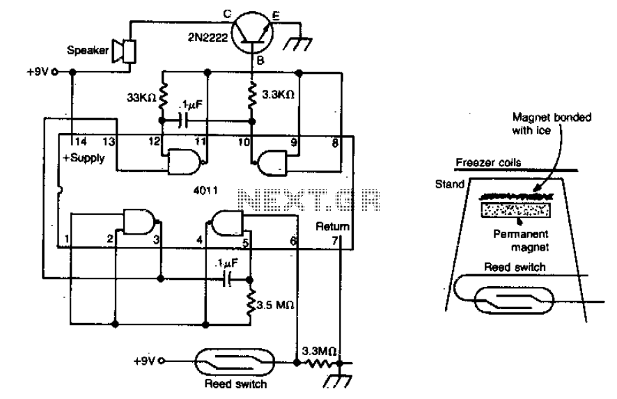
The meltdown consists of a magnet secured to a small stand by ice. A reed switch is positioned beneath the magnet. When the ice melts, the magnet drops onto the switch, closing it and completing the alarm circuit. The described...

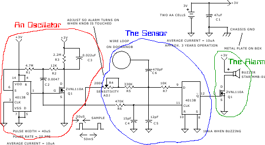
This circuit schematic produces a beep and/or illuminates an LED when someone touches the door handle from outside. The alarm will continue to sound until the circuit is switched off. The circuit operates on the principle of capacitive sensing, where...
This alarm siren circuit produces a warbling sound, suitable for use in toys or security alarms. The circuit employs two 555 IC oscillators. The first oscillator generates the audio frequency, while the second oscillator creates a modulating signal. This...
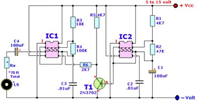
Browse home alarm circuit explanation latest schematic siren wailing with latest Wailing Alarm Siren circuit schematic with explanation. The loudspeaker LS and the resistor marked Rx should be together 75 ohms. If a standard 8-ohm speaker is used, then...