
Fading LED blinker


The collector of Q2 drives a low value resistor so this stage can supply enough current to drive the LED. The only problem here is that the pulses coming from the collector of Q2 are about 1.4 volts peak-to-peak, and a red LED needs close to 2 volts to operate. The trick that gets around the problem is to alternately charge a capacitor to 1.5 volts, then place it in series with the 1.5 volt battery and an LED, so the LED can get up to 3 volts.
The circuit design involves several key components working together to achieve the desired LED flashing effect. The LED Power Supply Oscillator/Driver is responsible for providing the necessary voltage and current to the LED. This section utilizes a bistable multivibrator configuration with transistors Q1 and Q2, which oscillates at approximately 15 kHz. This frequency is chosen to ensure that the LED can be flashed at a visually appealing rate. The duty cycle of around 50% allows for a balanced on-off time, contributing to the overall effectiveness of the blinking LED.
The Blink Rate Oscillator serves to control the timing of the LED flashes. This oscillator can be adjusted to modify the flash rate, allowing for customization based on user preference or specific application needs. By varying the resistance and capacitance in this section, the rate of blinking can be fine-tuned.
The Power Modulator section is crucial for controlling the luminance of the LED. By adjusting the drive current, this stage can create a fading effect, simulating the slower rise and fall of incandescent lamps. This modulation is achieved through the use of additional capacitors and resistors, which work together to create a smooth transition in brightness.
In summary, the circuit is designed to provide a realistic LED flashing effect that mimics traditional incandescent lights. The combination of a reliable oscillator, adjustable blink rate, and effective power modulation results in an enhanced visual experience that meets the requirements of a 1970's style caboose marker light. The design is robust, ensuring that the LED operates effectively within the constraints of a low voltage power supply, while also offering flexibility for customization. The lower the voltage, the easier it would be to fit the batteries into the caboose along with the flasher circuit. The venerable LM3909 LED flasher came to mind, but when it flashed, the LED only emitted a tiny blink, nothing the sustained flash on a real 1970's style caboose marker light.
He needed a circuit that would provide a longer flash. And while we are at it, how about making the luminance of the LED quickly fade up and then quickly fade down similar to the appearance of the real thing. Incandescent lamps take many milliseconds to reach full luminance and even longer to die down, while LEDs switch on and off virtually instantaneously, giving a distinctly different visual experience.
The resulting circuit can be customized to flash the LED at a wide range of rates, keeping the LED over a wide range of duty cycles. In addition, it can be made to allow the luminance to increase and decrease faster or more slowly as needed, and the drive current to the LED can be decreased to obtain the desired luminance.
Click on Movie 1 to see what the blinking of the LED looks like with the circuit values shown in the schematic in figure 1. The circuit can be thought of as being made from three major blocks: an LED Power Supply Oscillator/Driver, a Blink Rate Oscillator, and a Power Modulator to modulate the drive power to the LED, thus blinking it on and off.
The discussion of the LED Power Supply Oscillator / Driver assumes that the LED is "on" -that is the signal from the Blink Rate Oscillator is always high, and this is modeled in the circuits in the description of the LED Power Supply Oscillator / Driver by showing the emitter of Q2 grounded. The Led Power Supply Oscillator / Driver shown in Figure 2 is a pretty good little 1.5 volt LED power supply.
An oscillator, a bistable multivibrator made of Q1 and Q2 oscillates at about 15 kHz with approximately a 50% duty cycle. There are many explanations of multivibrators on the web, so I will not discuss it here, except to say that the main weakness of this kind of oscillator is that if it ever stops, it needs to be "kicked" back into oscillation.
A suitable "kick" can be made by disconnecting and reconnecting the battery. Don't worry, its unlikely that the oscillators will stop spontaneously. If your oscillator ever stops while power is applies, it will most likely be the result of an intermittent connection of a temporary short circuit. These oscillators are very reliable. The collector of Q2 drives a low value resistor so this stage it can supply enough current to drive the LED.
The only problem here, is that the pulses coming from the collector of Q2 are about 1.4 volts peak-to-peak, and a red LED needs close to 2 volts to operate. The trick that gets around the problem is to alternately charge a capacitor to 1.5 volts, then place it in series with the 1.5 volt battery and and LED, so the LED can get up to 3 volts.
🔗 External reference
Related Circuits

This is a compact LED flasher circuit designed using the 555 timer integrated circuit (IC), powered by two 1.5V batteries. The circuit can function as a flashing metronome, dark room timer, reminder, or for other similar applications. In the...
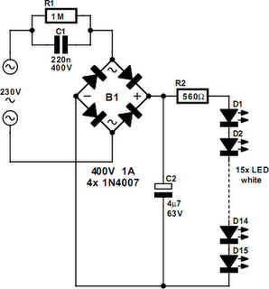
An array of white LEDs can serve as a compact lamp for living spaces. These LED lamps are commercially available and resemble standard halogen lamps, fitting into typical 230-V light fixtures. Upon inspection, it is evident that a capacitor...
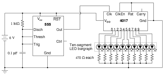
The model 4017 integrated circuit is a CMOS counter with ten output terminals. At any given time, one of these ten terminals will be in a "high" state, while all others remain "low," resulting in a "one-of-ten" output sequence....
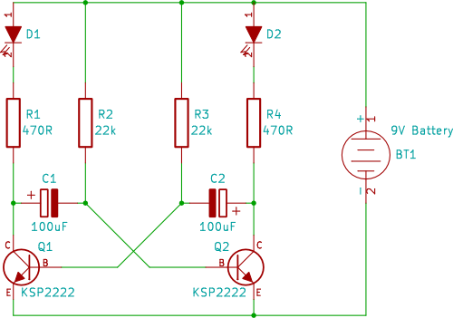
A two-transistor circuit that alternately flashes two LEDs on and off. This tutorial demonstrates how beginners in electronics can build this simple circuit on a breadboard. This circuit utilizes two NPN transistors configured in a flip-flop arrangement, which allows for...
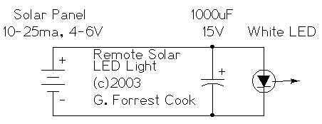
The remote solar powered LED light takes advantage of the current limited nature of solar photovoltaic cells. If light shines on the solar array, current will flow through the circuit. For a typical size of solar cell, there is...
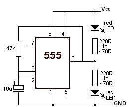
This LED flasher circuit utilizes a 555 timer integrated circuit (IC). The circuit diagram is straightforward and requires only a few external components. When operational, the red LEDs will flash sequentially at a predetermined frequency, similar to the indicators...