
LED sequencer

The model 4017 is a versatile CMOS decade counter, ideal for applications requiring sequential output control, such as LED displays, frequency division, and event counting. The counter operates by incrementing its output state in response to clock pulses, with a unique output activated at each step. The integration of a 555 timer as an oscillator allows for easy manipulation of the output frequency, making it suitable for various timing applications.
In practical applications, the 4017 can be interfaced with various components, including LEDs, relays, and other digital logic devices. The outputs can drive small loads directly or control larger loads through transistors or other driver circuits. The reset and clock enable functionalities provide additional control over the counting sequence, allowing for flexible operation in dynamic environments.
For circuit design, ensure proper power supply decoupling to maintain stable operation, especially when driving multiple outputs or when subjected to varying load conditions. The use of bypass capacitors close to the power supply pins of the 4017 can help mitigate noise and ensure reliable performance. Furthermore, careful selection of timing components in the 555 timer circuit will yield desired flashing rates and enhance the visual effect of the LED sequence.
Overall, the 4017 integrated circuit, when paired with a 555 timer, presents a robust solution for generating controllable sequences of events, making it a popular choice in educational projects, hobbyist applications, and even in professional designs requiring simple counting and timing functions.The model 4017 integrated circuit is a CMOS counter with ten output terminals. One of these ten terminals will be in a "high" state at any given time, with all others being "low, " giving a "one-of-ten" output sequence. If low-to-high voltage pulses are applied to the "clock" (Clk) terminal of the 4017, it will increment its count, forcing the next
output into a "high" state. With a 555 timer connected as an astable multivibrator (oscillator) of low frequency, the 4017 will cycle through its ten-count sequence, lighting up each LED, one at a time, and "recycling" back to the first LED. The result is a visually pleasing sequence of flashing lights. Feel free to experiment with resistor and capacitor values on the 555 timer to create different flash rates.
Try disconnecting the jumper wire leading from the 4017`s "Clock" terminal (pin #14) to the 555`s "Output" terminal (pin #3) where it connects to the 555 timer chip, and hold its end in your hand. If there is sufficient 60 Hz power-line "noise" around you, the 4017 will detect it as a fast clock signal, causing the LEDs to blink very rapidly.
Two terminals on the 4017 chip, "Reset" and "Clock Enable, " are maintained in a "low" state by means of a connection to the negative side of the battery (ground). This is necessary if the chip is to count freely. If the "Reset" terminal is made "high, " the 4017`s output will be reset back to 0 (pin #3 "high, " all other output pins "low").
If the "Clock Enable" is made "high, " the chip will stop responding to the clock signal and pause in its counting sequence. If the 4017`s "Reset" terminal is connected to one of its ten output terminals, its counting sequence will be cut short, or truncated.
You may experiment with this by disconnecting the "Reset" terminal from ground, then connecting a long jumper wire to the "Reset" terminal for easy connection to the outputs at the ten-segment LED bargraph. Notice how many (or how few) LEDs light up with the "Reset" connected to any one of the outputs: Counters such as the 4017 may be used as digital frequency dividers, to take a clock signal and produce a pulse occurring at some integer factor of the clock frequency.
For example, if the clock signal from the 555 timer is 200 Hz, and the 4017 is configured for a full-count sequence (the "Reset" terminal connected to ground, giving a full, ten-step count), a signal with a period ten times as long (20 Hz) will be present at any of the 4017`s output terminals. In other words, each output terminal will cycle once for every ten cycles of the clock signal: a frequency ten times as slow.
To experiment with this principle, connect your audio detector between output 0 (pin #3) of the 4017 and ground, through a very small capacitor (0. 047 µF to 0. 001 µF). The capacitor is used for "coupling" AC signals only, to that you may audibly detect pulses without placing a DC (resistive) load on the counter chip output.
With the 4017 "Reset" terminal grounded, you will have a full-count sequence, and you will hear a "click" in the headphones every time the "0" LED lights up, corresponding to 1/10 of the 555`s actual output frequency: In fact, knowing this mathematical relationship between clicks heard in the headphone and the clock frequency allows us to measure the clock frequency to a fair degree of precision. Using a stopwatch or other timepiece, count the number of clicks heard in one full minute while connected to the 4017`s "0" output.
Using a 1 M © resistor and 0. 1 µF capacitor in the 555 timing circuit, and a power supply voltage of 13 volts (instead of 6), I counted 79 clicks in one minute from my circuit. Your circuit may produce slightly different results. Multiply the number of pulses counted at the "0" output by 10 to obtain the number of cycles produced by the 555 timer during that same time (my circuit: 79 x 10 = 790 cycles).
Divide this number by 60 to obtain the number of timer cycle 🔗 External reference
Related Circuits
Alternative display methods exist beyond the original 8 LED frequency counter, potentially offering improved readability and a more suitable format for QRP equipment. This document presents examples of binary decimal displays. Typically, the counter omits the MHz position, focusing...
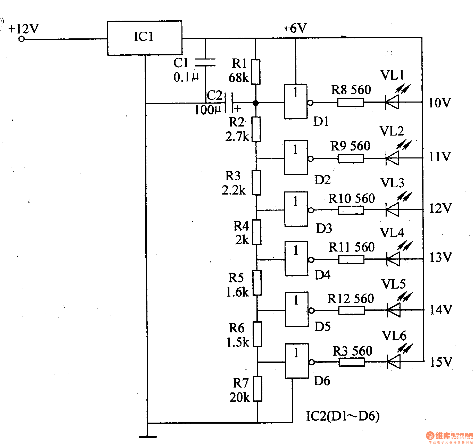
The LED car voltmeter comprises a filter circuit, a voltage distribution filter circuit, a voltage amplifier circuit, and an LED display circuit, as illustrated in Figure 7-77. The regulator filter circuit includes a 3-terminal IC (IC1) and a filter...
The LED flasher circuit operates by flashing an LED using only a 1.5-volt power supply. Typically, a power supply of more than 2 volts is required for an LED to function. The LED flasher circuit designed for operation at 1.5...
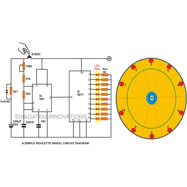
A simple circuit for a 10 LED roulette wheel is presented. Pressing the button initiates the LEDs in a rotational sequence that starts at full speed and gradually decelerates until it halts at a randomly selected LED. The randomness...
Each step will result in a self-functional unit. By the end of this process, it will be possible to link the steps together into a powerful FM transmitter. This section will explain the main controlling unit for the FM...
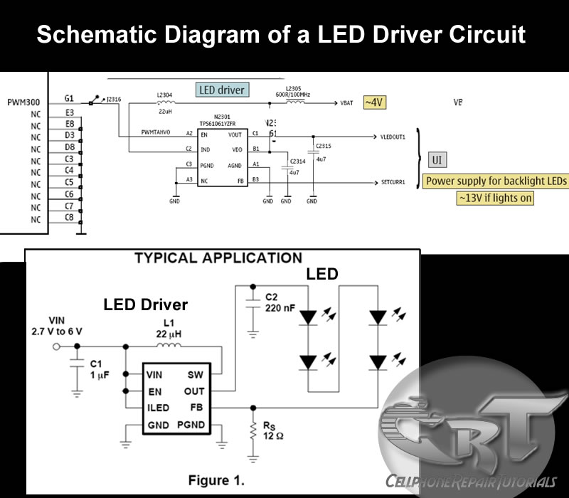
An LED (light-emitting diode) is utilized to illuminate keypad keys and LCD screen displays on all mobile phone handsets. It is controlled by the voltage or current drawn at its terminals. In the schematic diagram, the LEDs are driven...