
Fairy Flashing LED Lights

The circuit operates on a straightforward principle where the flashing LED acts as a pulse generator, creating a square wave signal that drives the base of the NPN transistor. This type of transistor is commonly used in low-power applications and is ideal for switching operations. The resistors in the circuit serve to limit the base current to the NPN transistor, ensuring that it operates within safe parameters while being driven by the oscillating signal from the flashing LED.
When the NPN transistor is turned on, it allows current to flow through the connected string of LEDs, illuminating them. The forward voltage drop across each LED must be considered to ensure that the total voltage drop does not exceed the supply voltage. The alternating flashing effect can be achieved by adding a PNP transistor, which is configured to turn on when the NPN transistor is off, thus creating a complementary flashing pattern between the two LED strings.
In terms of power supply, the use of an unregulated 12 V source is suitable for this circuit, but care must be taken to ensure that the supply voltage does not exceed the maximum ratings of the components used. The absence of a current-limiting resistor in the LED chain simplifies the design, but it requires precise matching of the forward voltage characteristics of the LEDs to avoid overcurrent conditions.
Overall, this circuit provides a versatile and engaging way to create visual effects using LEDs, suitable for various applications beyond just holiday decorations. By experimenting with different LED colors and configurations, users can customize the flashing patterns to suit their preferences, making it a fun and educational project for electronics enthusiasts.This simple and cheap circuit is not just for Christmas! There are just two resistors, a small-signal transistor such as a BC547, one flashing` LED and a string of normal` LEDs. The flashing LED works as an oscillator and switches the transistor on and off; and the transistor switches all the other LEDs.
An (unregulated) 12 V mains supply can be u sed for power. No current-limiting resistor is required in the LED chain, because the forward voltages of the LEDs in the chain add up to the supply voltage. If red LEDs are used, with a voltage drop of 1. 65 V, then 12 V will supply seven; alternatively, use six yellow (2. 1 V each) or five green (2. 7 V). You can of course always mix the colours. Alongside the NPN transistor add a PNP transistor with its emitter connected to +12 V, with another string of LEDs connected down to ground.
The two strings will flash alternately. Be the first of your friends to get free diy electronics projects, circuits diagrams, hacks, mods, gadgets & gizmo automatically each time we publish. Your email address & privacy are safe with us ! 🔗 External reference
Related Circuits
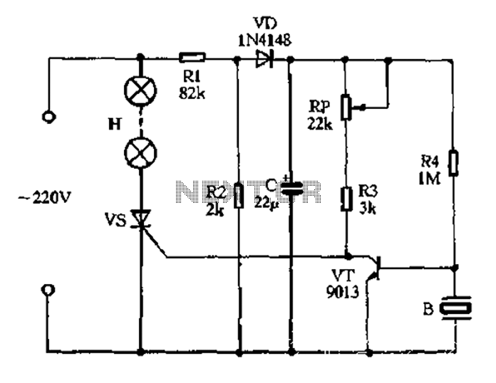
The circuit operates on 220V AC, utilizing resistors R1 and R2 to create a partial voltage drop. A VD half-wave rectifier converts this AC voltage to approximately 3V DC across capacitor C. An adjustment potentiometer RP is incorporated to...
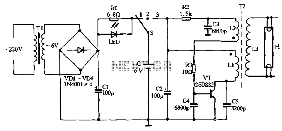
The charging circuit comprises a transformer (Tl), diodes (VDI-VD4), and various additional components. It operates on 220V AC, with the transformer Tl stepping down the voltage, while diodes VDI-VD4 perform rectification. A smoothing filter (CI) converts the rectified output...

VD1, VD2, C1, and C2 comprise a simple half-wave rectifier capacitor step-down voltage regulator circuit, providing an output of approximately 12V for a linear power supply connected to the LM386. The LM386 is linked to the inverting input terminal...

The goal was to create a compact flashlight that could be held in the mouth, easily stored in a pocket, and positioned on a surface to project light upwards. The budget was set at approximately $15, which was significantly...
Mobile batteries typically have a lifespan of 2 to 5 years under normal usage, after which they need to be replaced. Currently, inexpensive replacement batteries are available for about $1, but these low-cost options only last 6 to 12...
This circuit provides a visual 9-second delay using 10 LEDs before closing a 12-volt relay. When the reset switch is closed, the 4017 decade counter resets to the 0 count, illuminating the LED driven from pin 3. The 555...