
The easiest musical voice lights

The described circuit is a sound-activated light system that employs basic electronic components to achieve its functionality. The use of resistors R1 and R2 creates a voltage divider, which is essential for stepping down the 220V AC to a manageable level for the rectifier. The half-wave rectifier, denoted by VD, allows only one half of the AC waveform to pass, which is then smoothed by capacitor C to provide a steady DC voltage for the circuit's operation.
The adjustment potentiometer RP serves a critical role in fine-tuning the sensitivity of the sound detection mechanism. By varying the resistance, it alters the voltage at the base of transistor VT, which controls its conduction state. This responsiveness to sound is facilitated by the piezoelectric component B, which efficiently converts acoustic energy into an electrical signal. The interaction between the acoustic signal and the electronic components enables the system to respond dynamically to environmental sounds.
When the system detects a sound, the resulting electrical signal triggers the conduction of the transistor VT, which in turn activates the SCR vs. The SCR acts as a switch that allows current to flow to the light source, illuminating it in response to the detected sound. The configuration of three diodes ensures that the signal is appropriately processed to maintain consistent operation.
This circuit design is suitable for applications such as decorative lighting that responds to music or ambient noise, creating an engaging visual experience. The ability to adjust sensitivity through potentiometer RP allows for customization based on the environment, making it versatile for different settings. Overall, this sound-activated lighting system exemplifies a practical application of basic electronic principles to achieve an interactive and visually appealing effect.220V AC by Rl and R2 partial pressure, VD half-wave rectifier, the capacitor C in the left ends of about 3V DC voltage right. Adjustment potentiometer RP, so that the three-pol e tube VT just in the conduction state, then SCR vs gate and cathode is between the transistor VT ce very short road, vs, no trigger current in the off state, the color lights not bright. B for the piezoelectric ceramics, it receives into the environment after the acoustic signal output corresponding electrical signal, the electrical signal applied to the VT base and emitter, a negative half cycle of the signal so that the three diodes exit conducting state, which set That electrode vs SCR gate potential rises, vs open, lights on the light.
So lantern can with the music and sparkling acoustic environment. Potentiometer RP can be used to adjust the voice sensitivity. RP tune hours, the transistor VT conduction shallow depth, VT easy to withdraw a short guide state, so the voice is high sensitivity {On the contrary, when the big tune RP, VT deep saturation, VT exit to the conduction state needs to enter a larger base signal, dare voice low sensitivity.
Related Circuits

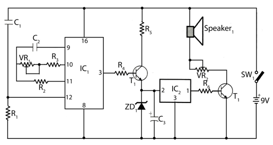
This document describes a family karaoke lighting design that employs various methods to control the circuit. The control circuit presented here features a four-way light output with loop jumping and speed control capabilities. The practical circuit utilizes a microphone...

An efficient automatic solar garden lights circuit with minimal components. The notable feature is that it operates entirely automatically, with the solar panel functioning as a light detector. The automatic solar garden lights circuit is designed to provide illumination in...

An array of white LEDs can serve as a small lamp for the living room. LED lamps are readily available, resembling standard halogen lamps, and can be installed in a standard 230-V light fixture. A capacitor is employed to...

This circuit detects the presence of audio (voice) on the output of a scanner. If the scanner stops on a "dead carrier" or noise, the circuit mutes the speaker to avoid annoying noise. An operational amplifier amplifies speech and...

The following circuit illustrates the CD4017 integrated circuit (IC) used in an automatic room lights sensor circuit diagram. Features include a single light sensor utilizing two light-dependent resistors (LDRs). The CD4017 is a decade counter IC that can drive multiple...
The circuit timer with a musical alarm utilizes a well-known CMOS oscillator/divider integrated circuit (IC1). Although this circuit operates at 9V, its standby current drain is minimal. The time delay of the timer circuit can be adjusted by modifying...