
LM386 making music with a voice-activated lights circuit

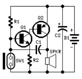
The circuit functions as a basic power supply and signal processing unit. The half-wave rectifier formed by diodes VD1 and VD2, along with capacitors C1 and C2, provides a regulated DC voltage output suitable for powering the LM386 audio amplifier. This amplifier is specifically designed to operate with low-voltage power supplies and is capable of amplifying low-level audio signals from the piezoelectric sensor.
The piezoelectric ceramic sheet acts as a transducer, converting mechanical vibrations from the environment into electrical signals. When acoustic waves strike the piezoelectric material, it generates a voltage proportional to the intensity of the sound. This voltage is fed into the LM386, where it is amplified to a usable level.
The output from the LM386 (pin 5) is coupled through capacitor C4 to the gate of the thyristor. The thyristor's conduction angle is controlled by the amplified signal, effectively modulating the power delivered to the lantern string H. As the acoustic signal strength varies, the intensity and flash rate of the lantern's light output correspondingly change, creating a visual representation of the surrounding acoustic environment.
This circuit design is particularly useful in applications where visual indicators are needed to represent sound levels, such as in sound-activated lighting systems or audio-responsive decorations. The integration of the piezoelectric sensor with the LM386 amplifier and the thyristor control allows for a compact and efficient system capable of real-time response to environmental sounds.VD1, VD2, C1 and C2 form a simple half-wave rectifier capacitor step-down voltage regulator circuit, the output of about 12V in straight right current voltage supply manifold LM386 electricity. LM386 connected to the inverting input terminal 3 feet inside the piezoelectric ceramic sheet B receiving environment acoustic signal and converts it into a corresponding electrical signal, amplifying circuit after the internal manifold by 5 feet output by C4, T bidirectional drive thyristor vs, make vs conduction angle B with signals picked up strength and change, so can make the lantern string H with flashing light and acoustic environment signal strength.
Related Circuits
The system involves positioning a small magnet near the stalk switch SW1, which is connected to the hand or garments of the individual carrying the bag via a tiny cable. Due to the compact nature of the circuit, it...
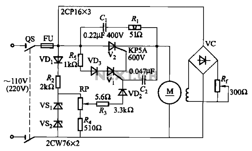
A 100W resistance-triggered motor control circuit designed for arc welding machines. It features an adjustment potentiometer (Rr) that can modify the DC motor excitation current. Additionally, a regulator (RP) is included to adjust the DC motor armature voltage, enabling...
Switch S2 is used for increasing and switch S3 is used for decreasing the volume. Similarly, switches S4 and S5 are provided for second channel (right channel) volume control. Also, pin 14 of IC2 can be connected to IC...
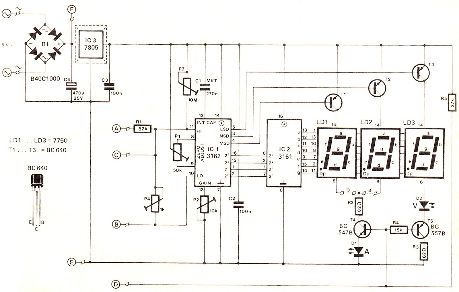
This voltage/current (V/I) display module is well-suited for integration into an existing DC power supply, providing precise readings of the set voltage or the current consumption of the load. The voltage measurement range features a decimal point indicator (LD3),...
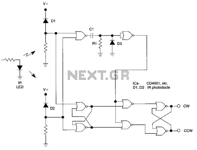
The circuit utilizes two CD4001 packages, incorporating eight NOR gates. It operates by receiving pulse streams that are input to an RS flip-flop, producing an output waveform with a variable duty cycle based on the direction of rotation. The...

A pH electrode measures hydrogen ion (H+) activity and generates an electrical potential or voltage. The operation of the pH electrode is based on the principle that an electric potential develops when two liquids of different pH come into...