
Fast acting power supply protection

If the voltage at the regulator output exceeds 13 V, the zener diode enters breakdown mode and activates the thyristor, which then shorts the supply line and causes the main fuse to blow.
The described circuit provides a robust solution for overvoltage protection in regulated power supply systems. The primary components include a voltage regulator, a zener diode, a thyristor, and a fuse. The voltage regulator is responsible for maintaining a stable output voltage, while the zener diode serves as a voltage reference. When the output voltage approaches the predefined threshold of 13 V, the zener diode will conduct in reverse breakdown, allowing current to flow through it.
This current triggers the thyristor, a semiconductor device that can conduct current in one direction when it is activated. Once the thyristor is turned on, it creates a low-resistance path to ground, effectively shorting the power supply output. This action diverts the excess voltage away from the load, preventing damage to sensitive components. The main fuse in the circuit is designed to protect the entire system by breaking the circuit if the current exceeds a safe level, thus ensuring that no further damage occurs.
The choice of the zener diode is critical; it should be rated for the maximum voltage that the circuit is intended to handle. Adjusting the zener diode value allows for customization of the overvoltage threshold, making the circuit adaptable to various applications. The overall design emphasizes reliability and safety, ensuring that the load remains protected even in the event of a fault in the power supply.When using a regulated power supply to reduce a supply voltage, there is always the danger that component failure in the power supply might lead to a severe overvoltage condition across the load. To cope with overvoltage situations, the circuit is designed to protect the load under overyoltage conditions.
Component values given are for a 20 V supply with regulated output at 12 V. The zener diode can be changed according to whatever voltage is to be the maximum If the voltage at the regulator output rises to 13 V or above, the zener diode breaks down and triggers the thyristor which shorts out the supply line and blows the main fuse.
Related Circuits
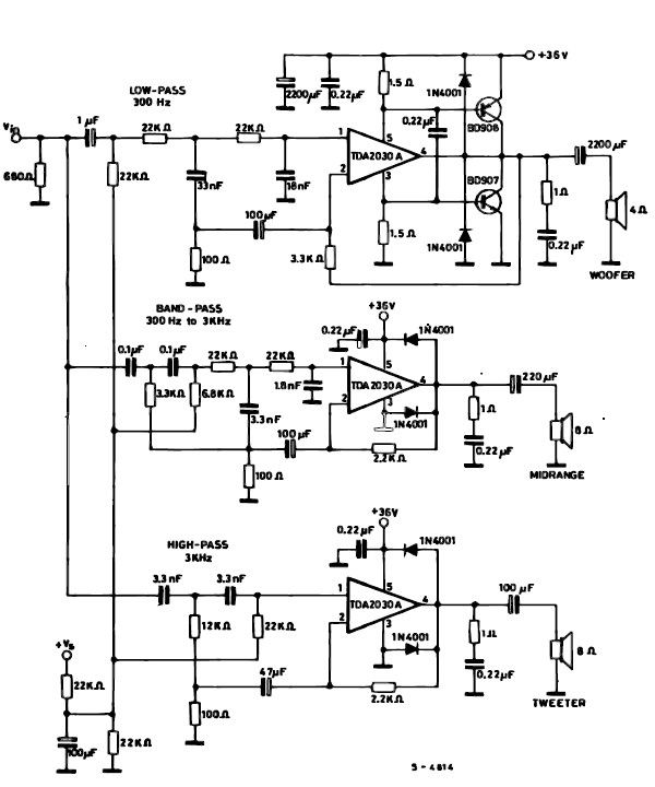
A simple multiway active speaker audio system can be designed using the TDA2030 audio IC. This TDA2030 active speaker audio system circuit is created to deliver optimal acoustic performance, as each loudspeaker is specifically designed and optimized for a...
This project uses the 1.2v rechargeable battery and solar panel from a Solar Garden Light. These lights can be bought for less than $5.00 in most $2.00 shops or similar shops that sell general household items. We are also...
The amplifier drives a pair of loudspeakers using two LM3876 integrated power amp ICs (50 watts per channel), or a pair of headphones via a Meier crossfeed filter and an OPA2134 dual opamp. It provides four switchable line level...
This application note demonstrates a simple 8-direction digital compass application utilizing Zilog's Z8 Encore!® MCU and an external compass sensor hardware. Communication ports are provided for the digital compass to receive commands and send status via the I2C bus...
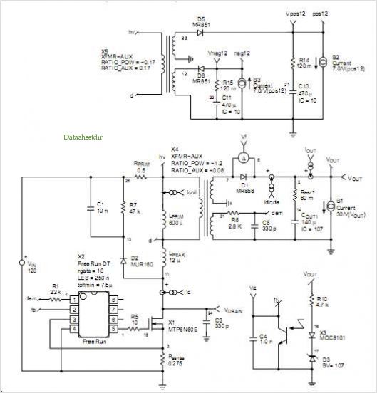
This power supply is designed as either an auxiliary or a permanent power supply for various common circuits that require a stabilized DC voltage ranging from 3 to 30V, provided that the current consumption does not exceed 3A. Additionally,...
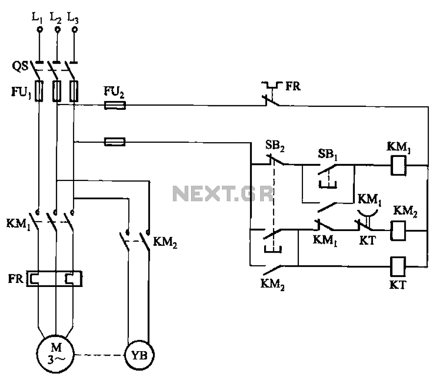
The circuit illustrated in Figure 3-123 operates as follows: When the stop button SBz is pressed, contact KMi releases, cutting off power to the motor. Simultaneously, KMz is activated, engaging the electromagnetic brake YB to hold the motor in...