
Fast Composite Amplifier Circuit

The device can be modified to provide an overall gain of 5 by adjusting both the R/Rm ratio and the R2/R1 ratio to 4:1. This adjustment increases the gains of the AD811 and the total circuit while keeping the AD797 at unity gain. Changing only the R/Rm ratio may lead to circuit instability, whereas altering only the R2/R1 ratio will allow the AD797 to operate at gain, resulting in a reduced overall bandwidth. The resistor Ri should be set to the parallel combination of Rm and Rf.
The described circuit utilizes a combination of high-performance operational amplifiers to achieve superior signal integrity and low distortion. The AD797, known for its ultra-low noise characteristics, is complemented by the high-speed capabilities of the AD811, creating a composite amplifier that excels in applications requiring high precision, such as analog-to-digital conversion and automated test equipment. The design emphasizes maintaining low total harmonic distortion, making it suitable for high-fidelity audio applications and sensitive measurement systems.
The operational amplifiers are configured to optimize their strengths; the AD811's higher gain compensates for the AD797's slower response, enabling efficient signal processing without sacrificing performance. The ability to modify the gain through resistor ratios provides flexibility in circuit design, allowing for adaptation to specific application requirements while ensuring stability and performance.
In practical implementation, careful selection of resistor values is crucial. The Ri value, determined by the parallel combination of Rm and Rf, plays a significant role in maintaining the desired bandwidth and stability of the system. The circuit's performance can be further enhanced by utilizing precision resistors and capacitors to minimize additional noise and distortion introduced by the components themselves. Overall, this composite amplifier circuit stands out as a robust solution for high-performance electronic applications. An ultra-low-noise, low-distortion op ampthe AD797is combined with the ADS 11 op amp, which offers a high bandwidth and a 100-mA output drive capability. The composite-amplifier circuit serves quite well when driving high resolution ADC`s and ATE systems.
The fast AD811 operates at twice the gain of the AD797 so that the slower amplifier need only slew one-half of the total output swing. Using the component values shown, the circuit is capable of better than -90 dB THD with a 5-V, 500-kHz output signal.
If a 100-kHz sine-wave input is used, the circuit will drive a 600- load to a level of 7 V rms with less than -109 dB THD, as well as a 10-kQ load at less than -117 dB THD. The device can be modified to supply ari overall gain of 5 by changing both the R/R-m ratio and R^R2 ratio to 4:1. This raises the gains of AD811 and the total circuit while maintaining the AD797 at unity gain. If only the R/Rm ratio is changed, the circuit might become unstable. In contrast, if only the RJR2 ratio is varied, the AD797 will then operate at gain. Subsequently, the circuit will have a lower overall bandwidth. Ri should be equal to the parallel combination of Rm and Rf.
Related Circuits
The Accu charger circuit is straightforward and simple to construct, requiring no more than ten components. In addition to its ease of assembly, this charger circuit is also cost-effective and highly efficient. The circuit requires a power supply from...
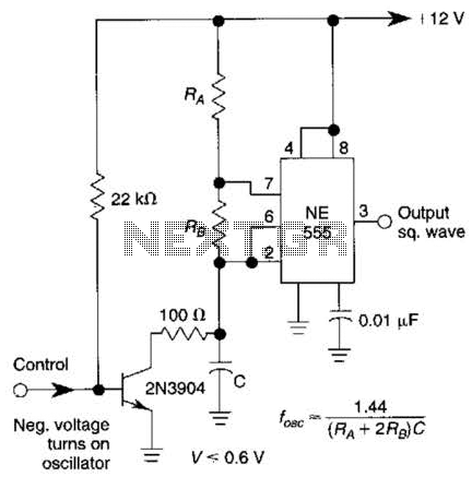
This gated 1-kHz oscillator provides a press-to-turn-on functionality, with waveforms available at the output of pin 3 and across capacitor CI. The gated 1-kHz oscillator circuit is designed to produce a square wave output that can be activated by a...
This oscillator is known as the Colpitts oscillator and is voltage-controlled to facilitate frequency modulation (FM) and phase-locked loop (PLL) control. The transistor T1 should be a high-frequency (HF) transistor for optimal performance; however, in this instance, a common...
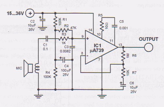
This circuit is a low voltage microphone preamplifier that operates with a 1.5V power supply. It features a reference with a 500 kHz unity-gain bandwidth, functioning as a preamplifier with a gain of 100. The output from this stage...
This guitar amplifier electronic architecture utilizes a robust conventional circuit design for the power amplifier, employing a single-rail supply of approximately 60V and capacitor coupling for the speakers. The advantages of this configuration for a guitar amplifier include a...
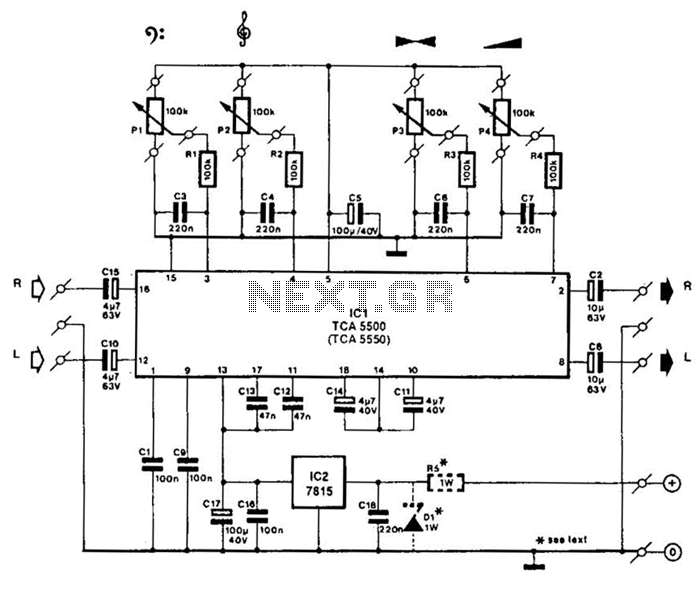
A Motorola TCA5500 or TCA5550 can be utilized to create a stereo preamplifier system equipped with tone controls. This circuit is designed to offer a gain of approximately 10 times, a tone-control range of 14 dB, and a volume...