
Fast Electronic Fuse

The electronic fuse circuit operates effectively on a 230V AC supply, providing a crucial safety mechanism for various loads. The adjustable trip current feature is achieved using a 1kΩ wire-wound potentiometer, which allows the user to set the desired current threshold. The wiper position on the potentiometer directly influences the trip current; as the resistance decreases, the trip current threshold increases, allowing for greater current to pass through before the fuse activates.
The circuit includes a series connection of power resistors, which play a vital role in monitoring the load current. These resistors generate a voltage drop that is proportional to the current flowing through them, enabling the circuit to detect when the load exceeds the pre-set limits. The voltage drop is measured and compared against a reference voltage within the circuit. When the load current surpasses the threshold determined by the potentiometer setting, the circuit triggers a mechanism to disconnect the load, effectively preventing damage from overcurrent conditions.
The switch S1 provides an additional layer of functionality by allowing the user to alter the trip current range. When S1 is in the open position, the circuit is designed to trip within a current range of approximately 300-650 mA. Conversely, closing S1 increases the trip current range to between 0.8A and 2A. This feature is particularly useful for applications where the load may vary significantly, allowing for quick adjustments to the protection level without the need for complex modifications to the circuit.
In summary, the electronic fuse circuit is a reliable protective device that employs adjustable settings to cater to different load requirements, ensuring that overcurrent conditions are swiftly addressed while maintaining the integrity of the connected equipment. The design emphasizes safety and adaptability, making it suitable for a wide range of applications in both residential and industrial environments.A fast electronic fuse designed to operate on 230V AC with an adjustable trip current. When the current through the load exceeds a level determined by the position of the wiper on the 1k wire-wound pot, this circuit cuts off the load immediately. If S1 is open, the range is approximately 300-650 mA, and 0.8-2A when it is closed. The key variable in the operation of the fuse is the voltage drop across the power resistor(s) which are connected in series with the load. This voltage drop is directly proportional to the current the load draws. When this current is low, the voltage acr 🔗 External reference
Related Circuits

This beginner's breadboard circuit simulates the action of throwing a dice. By pressing a button, the circuit generates a random output, lighting up one of six LEDs to represent the result of the throw. The circuit utilizes a microcontroller or...

The thermostat electric circuit operates as depicted in the figure. It has three settings: off, low power (Lo), and high power (Peru HL). When the DIP switch SA is set to the Lo position, 220V AC is directed through...

A simple lab power supply electronic project can be designed using this circuit diagram, which is based on the LM2576 monolithic integrated regulator that provides all the active functions for a step-down (buck) switching regulator. As seen in the...
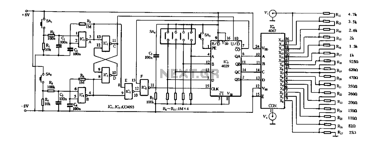
Figure 4-14 illustrates a digital integrated circuit featuring 16 preset potentiometers for Siniperca electronic circuits. The circuit comprises three main components: an input controller, a presettable counter, an analog electronic switch, and a resistor network. It includes a push-button...

This is the basis of electronics telephone sets. You can use it to replace the talking circuit of an old telephone set with new design, better noise rejection and reliability one. Also you can use it to build a...

A precision half-wave rectifier utilizing an operational amplifier will achieve a rectification accuracy of 1% from DC to 100 kHz. A precision half-wave rectifier circuit is designed to convert an AC signal into a unidirectional output while maintaining high accuracy...