
electronic dice

The circuit utilizes a microcontroller or a simple 555 timer-based design to achieve the randomization effect. When the button is pressed, it triggers the circuit to produce a random number between 1 and 6, which corresponds to the lighting of one of the six LEDs.
The components typically involved in such a circuit include:
1. **Microcontroller or Timer IC**: The 555 timer can be configured in astable mode to create a pulse output, while a microcontroller can be programmed to generate random numbers.
2. **Push Button Switch**: This input device allows the user to initiate the dice throw by closing the circuit momentarily.
3. **LEDs**: Six LEDs are used, each representing a face of the dice. They should be connected in such a way that only one LED lights up at a time based on the random output.
4. **Current-Limiting Resistors**: Resistors are necessary to prevent excessive current from flowing through the LEDs, thereby protecting them from damage.
5. **Power Supply**: A suitable power source, such as batteries or a DC power supply, is required to energize the circuit.
The circuit can be assembled on a breadboard for easy prototyping. Connections should be made carefully to ensure that the push button connects to the input of the microcontroller or timer, which in turn controls the output to the LEDs.
In summary, this circuit serves as an educational tool for beginners to learn about random number generation and basic circuit design while simulating a dice throw. The simplicity of the components involved makes it an excellent project for those new to electronics.This beginner`s breadboard circuit simulates a dice being thrown. Pressing the button throws the dice. One of six LEDs will light up after the throw.. 🔗 External reference
Related Circuits
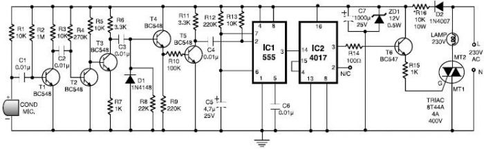
This 555 timer clap switch circuit electronic project is designed using common electronic components. The circuit operates from a distance of up to 10 meters from the microphone. The signal from the microphone is amplified by transistors T1, T2,...
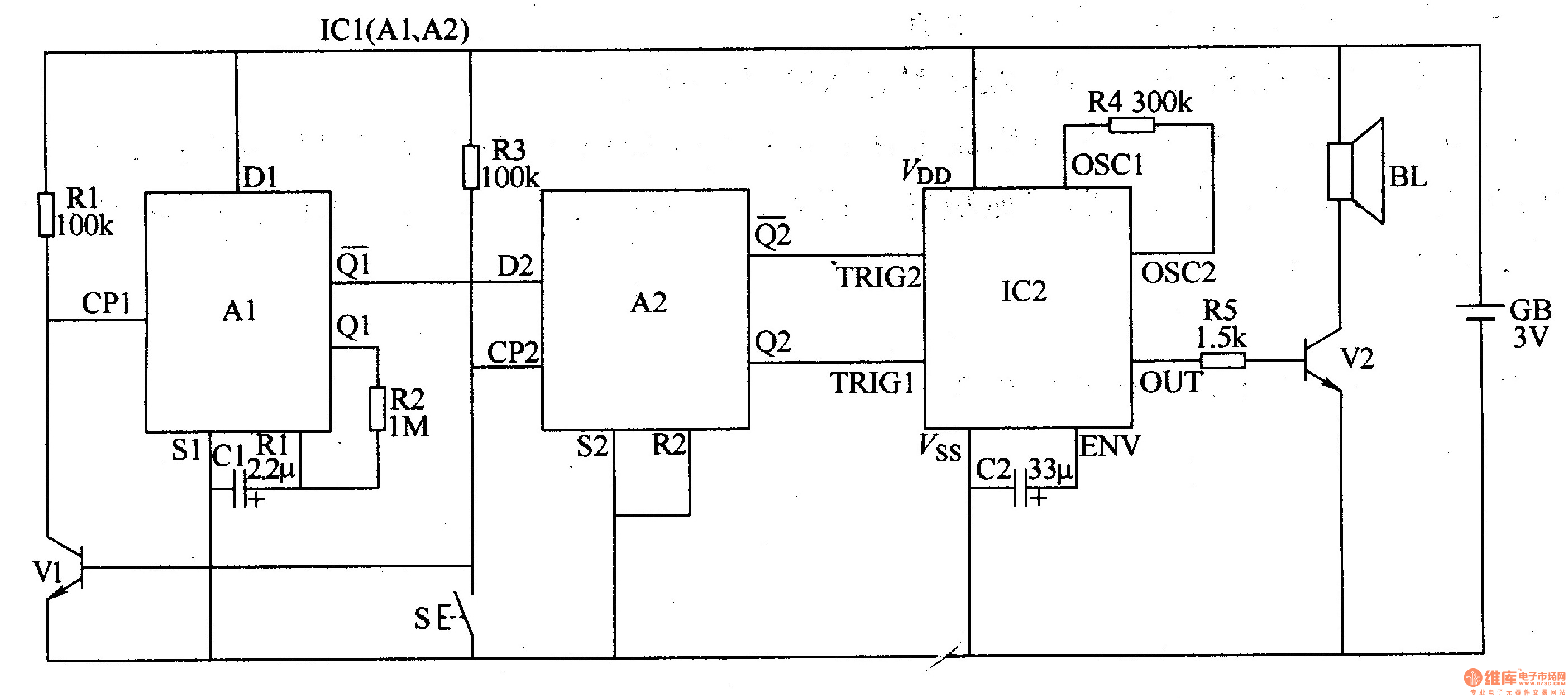
The two-tone electronic doorbell circuit consists of an input trigger circuit and an audio output circuit. The input trigger circuit includes a doorbell button (S), a transistor (V1), resistors (R1-R3), a capacitor (C1), and a dual D flip-flop integrated...

An AC magneto is connected to an external circuit. The output is rectified by diode D1 and stored in capacitor C1. Additional rectification is performed by diodes D4, along with resistors R9 and capacitors C7 and C8, which filter...
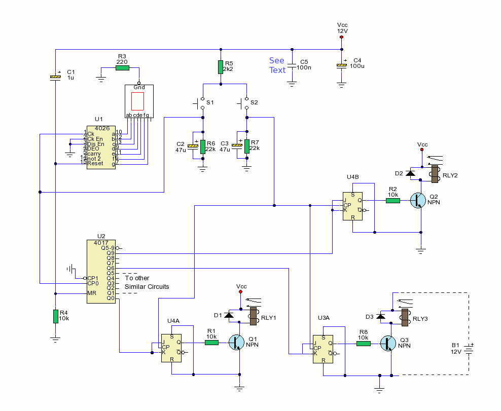
The schematic depicts two switches, S1 and S2, utilized for controlling the outputs. The primary function is executed by U2, a CMOS4017 decade counter divider integrated circuit (IC). Upon activation, capacitor C1 is swiftly charged through resistor R4, generating...
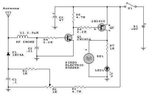
This electronic RF detector project is constructed using common transistors and a few standard electronic components. The RF detector is capable of responding to RF signals below the standard broadcast band and extending to over 500 MHz, providing both...
A simple forward-reverse motor control driver electronic circuit can be designed using the LB1948M, a two-channel low saturation voltage forward-reverse motor control driver IC. The LB1948M motor driver is suitable for use in 12V system products and can drive...