
Fast Low Duty-Cycle Pulse Oscillator

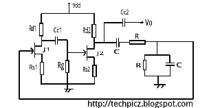
The described free-running generator circuit is a fundamental oscillator design that utilizes complementary transistor pairs to generate square wave signals. The circuit typically consists of two NPN and PNP transistors arranged in a feedback loop, allowing for symmetrical output waveforms. The output characteristics include a 50-ohm impedance, making it suitable for driving various loads, such as RF circuits or digital logic inputs.
The pulse width of 100 ns indicates that the generator can produce high-frequency oscillations, making it suitable for applications requiring fast switching times. The ability to operate across a wide voltage range (from below 1 V to above 15 V) adds versatility, allowing the circuit to be integrated into various electronic systems without stringent power supply requirements.
The design emphasizes low power consumption and minimal drift in voltage and temperature, which is critical for applications in precision timing and signal generation. The gain condition for the transistors ensures that the oscillation remains stable; if the gain drops below unity, the oscillator will cease to function. Therefore, careful selection of resistor values is essential to maintain the desired operating point and ensure reliable performance.
The RC timing networks play a crucial role in determining the frequency of oscillation. By adjusting the resistor (R) and capacitor (C) values, the timing characteristics can be fine-tuned. The longest time constant among the RC pairs will dictate the overall frequency, allowing for flexibility in design and implementation based on specific application requirements. This feature is particularly advantageous in applications where frequency modulation or signal shaping is necessary.
Overall, this free-running generator circuit is a robust solution for generating precise, high-speed oscillations in a variety of electronic applications, combining simplicity with effective performance. This simple and symmetrical free-running generator has a 50- output impedance, a pulse width of 100 ns and complementary outputs that swing essentially from ground to the power-supply voltage. Moreover, it functions with a power supply range from < 1 to > 15 V and maintains a low voltage and temperature drift while consuming little power. For oscillation to occur, each transistor must have a gain greater than unity. This restricts the value of R to a range of 1 kfi to 1, because the gain will be less than unity when the transistor is saturated or when beta is low as a result of small collector currents.
The two RC timing networks do not have to match because the RC with the longest time constant will determine the frequency of oscillation.
Related Circuits
A hybrid amplifier is being developed, utilizing an Aikido configuration for the voltage amplification stage (VAS) and an emitter-follower variation for the output stage (OPS). The hybrid amplifier design integrates two distinct amplification stages to achieve high performance and...
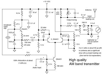
In many discussions of LPAM transmitter design, references to "the Wenzel circuit" or "the Wenzel transmitter" are common. These terms refer to a clever transmitter design that became popular in the mid-1990s and early 2000s for those interested in...
The Wien bridge oscillator utilizes a balanced Wien bridge as its feedback network. Two-stage common source amplifiers provide a 360-degree phase shift to the signal. The attenuation of the bridge is calculated to be 1/3 at the resonant frequency....
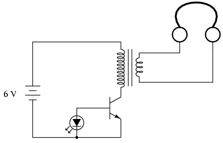
If you do not have an audio detector already constructed, a set of closed-cup audio headphones that completely cover the ears, along with a 120V/6V step-down transformer, can be utilized to create a sensitive audio detector for this experiment....

An early schematic of a Colpitts circuit utilizing a vacuum tube, redrawn from a patent publication. The Colpitts oscillator, invented in 1920 by American engineer Edwin H. Colpitts, is one of several designs for electronic oscillators. The Colpitts oscillator is...
This simple battery charger circuit is designed for NiMH/NiCd batteries. It requires no microcontroller or any programming. Linear Technology Corporation. The described battery charger circuit is intended for use with nickel-metal hydride (NiMH) and nickel-cadmium (NiCd) batteries, which are commonly...