
Fast Voltage-Driven Current Source

The current source depicted in the schematic is designed to provide a stable output current that responds rapidly to variations in the input signal. This characteristic is particularly beneficial in applications requiring precise measurements, such as in differential measurement systems. The ability to react swiftly to input changes ensures that the current source can accurately track dynamic signals, minimizing lag and improving measurement fidelity.
In a typical configuration, the current source may utilize operational amplifiers to regulate the output current. The feedback mechanism employed in the design allows for quick adjustments in response to fluctuations in the input signal, thus maintaining a consistent current output. The differential nature of the current source can be advantageous in reducing common-mode noise, enhancing the overall signal integrity during measurement operations.
Furthermore, the current source may be integrated into various electronic systems, such as analog-to-digital converters (ADCs) or sensor interfaces, where rapid response times are critical. The design should also consider factors such as temperature stability and power supply variations, ensuring reliable performance across a range of operating conditions. Overall, the current source serves as a vital component in high-precision measurement applications, contributing to improved accuracy and reliability.The current source in the diagram, which react very fast to changes in the input signal, may be used, for instance, in certain measurements. Differential.. 🔗 External reference
Related Circuits
Tests 1.5 to 15 Volt cells. This circuit runs a fast battery test without the need of power supply or expensive moving-coil voltmeters. It features two ranges: when SW1 is set as shown in the circuit diagram, the device...
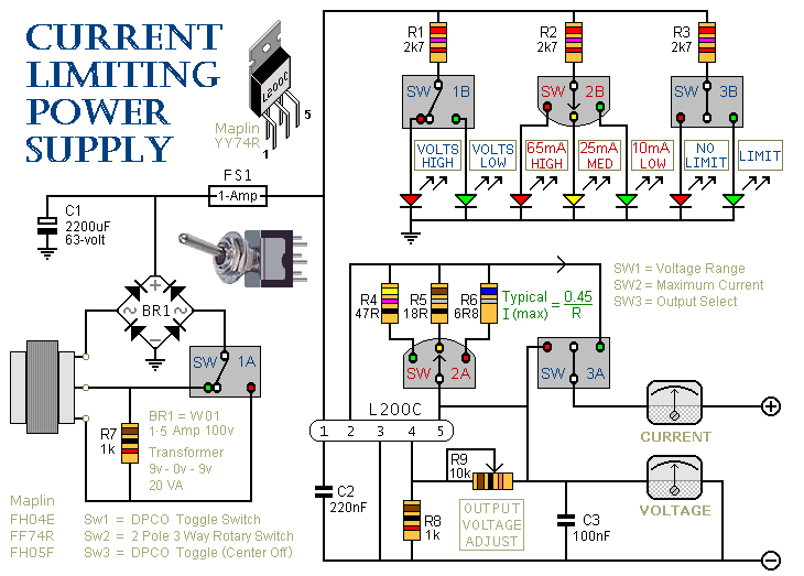
SW3 is the on/off switch. It also lets you choose between the output with the current limit and the one without. SW2 provides a selection of three different limits. You can increase or decrease this number if you wish....
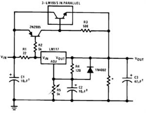
The LM117/LM317 from National Semiconductor Corporation is a three-terminal adjustable positive voltage regulator integrated circuit (IC). The output voltage range of the LM117/LM317 is from 1.2V to 37V with a load current capability of up to 1.5A. It is...
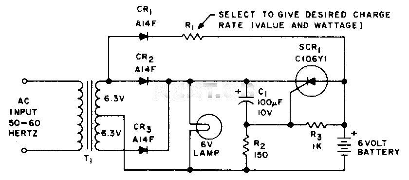
This emergency lighting system maintains a 6-volt battery at full charge and automatically switches from the AC supply to the battery. The emergency lighting system is designed to ensure reliable illumination during power outages or failures. It consists of a...
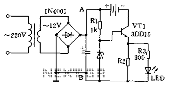
A practical single-tube constant current charger is illustrated, utilizing a transistor (VT1) that plays a crucial role in maintaining a constant current. The current value is determined by the voltage regulator and resistor R2. The general output voltage is...
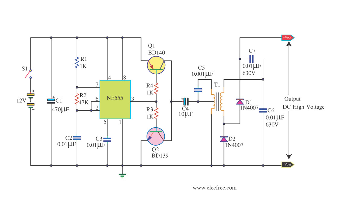
This circuit is a DC to DC inverter that can convert a 12V DC battery voltage to a high voltage of 300V DC. This circuit operates with low current. This DC to DC inverter circuit is designed to efficiently step...