
Single-tube constant current charger circuit

A single-tube constant current charger operates by regulating the current flowing into the battery pack using a transistor (VT1). The design features a voltage regulator that outputs approximately 3.3V, which is essential for the proper charging of nickel-cadmium batteries. Resistor R2 plays a pivotal role in setting the charging current, which can be adjusted within the range of 50mA to 80mA, depending on the specific resistance value chosen. The resistive load of R2 should be selected within the range of 30 to 60 ohms and rated for 1W to 2W to handle the power dissipation effectively.
In conjunction with the LED indicator, resistor R3, with a value between 200 to 500 ohms, is used to signal the charging status. When the circuit is operational and batteries are connected, the LED will illuminate, indicating that charging is taking place. A non-illuminating LED suggests a potential issue with the batteries, warranting further investigation.
The charger is capable of charging between 1 to 4 nickel-cadmium batteries, with a recommended charging time of approximately 12 to 14 hours, depending on the battery's state of charge and capacity. The choice of transistor, such as the 3DD15 or DS11, is critical for effective power management. It is advisable to attach a heat sink to the VT1 transistor to mitigate overheating during operation, ensuring reliability and longevity.
As there is no built-in charge control circuit, users must diligently monitor the charging time to prevent overcharging, which could lead to battery damage or reduced lifespan. This aspect emphasizes the importance of user awareness and adherence to safe charging practices when utilizing this charger design. As shown in a practical single-tube constant current charger, which play a constant role transistor VT1, its current value is determined by the voltage regulator and R2. Genera l election regulator about 3.3V, resistor R2 taken (30 to 60 Euro)/(1W ~ 2W), when the charge current is about 50mA ~ 80mA. R3 (200 ~ 500 ohms) and LED charging indicator composition circuit is connected as long as rechargeable batteries, LED will glow.
If the LED does not light, the battery is bad. The circuit of 1 ~ 4 5 nickel-cadmium batteries, charging time is 12 to 14 hours. Transistor VT1 available 3DD15 or DS11 (plastic) power management, installation, VT1 tube should be added to the radiator. Two kinds of charger neither add charge control circuit should be used to grasp the charging time, in order to ensure safe charging.
Related Circuits

The hobby circuit described utilizes a unique approach to generate approximately 12,000 volts with a current of about 5 µA. It employs two silicon-controlled rectifiers (SCRs) that form dual pulse generator circuits. These SCRs discharge a 0.047 µF capacitor...
Here is a circuit diagram for adjusting the brightness of a light bulb. The second battery is utilized to power the circuit. This circuit can be used to modify the brightness of images during close-up photography with a digital...
The LM380 is a power audio amplifier designed for consumer applications. To minimize system costs, the gain is internally fixed at 34 dB. It features a unique input stage that allows for ground-referenced input signals. The output automatically self-centers...
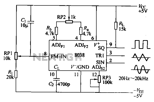
The ICL8038 function generator is an audio composition device that utilizes the ICL8038 integrated circuit. The resistance Ri potentiometer RP1 is used to determine the flow potential. Typically, the output is set to approximately 2Vcc / 3. Lowering the...
This page shows some methods of track routing control for Stall-Motor type switch machines. The principle method uses a 2 Pole - Multi Position rotary switch while an alternate uses optoisolators and transistors to select the routes. The last...
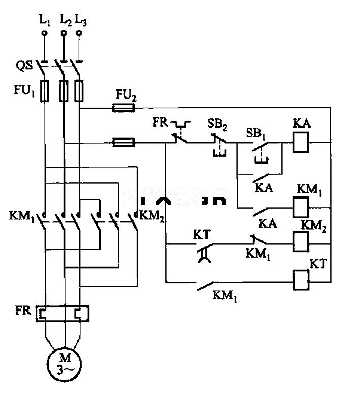
The circuit illustrated in Figure 3-127 utilizes a time relay (KT) in place of a speed relay. The timing duration is adjustable and typically set between 1 to 2 seconds. This circuit is designed to operate effectively in dusty...