
UJ-1 type potentiometer with a precision power supply circuit

The described circuit employs a transistor (VT) in conjunction with a voltage regulator (VSL) to establish a constant current source. This configuration is particularly advantageous in applications requiring stable current output regardless of variations in load or supply voltage. The inclusion of three regulators in the design serves to improve the overall performance and reliability of the circuit.
The first regulator in the series can be configured to provide a stable reference voltage, ensuring that the subsequent stages operate within their optimal parameters. The second regulator can be employed to regulate the output voltage, allowing for fine-tuning of the output current. The third regulator functions as a protection mechanism, safeguarding the circuit against overcurrent conditions and ensuring longevity and stability in operation.
In this configuration, the transistor (VT) acts as a control element, responding to the feedback from the voltage regulators to maintain a constant output current. The combination of these components results in a robust circuit capable of delivering precise current levels, making it suitable for various applications in electronic devices, such as LED drivers, battery chargers, and precision measurement instruments. The overall design emphasizes efficiency, stability, and protection, which are critical in high-performance electronic systems. By the transistor VT and regulator vsl etc. constant current source, and the use of three regulator, the regulator circuit therefore of high pulp.
Related Circuits
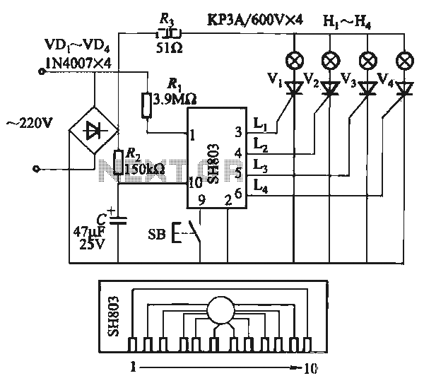
The circuit utilizes the SH803 flash IC, which can store eight different programs and offers various dimming options and light speed adjustments. A button is provided to trigger the control terminal SB on the 9-pin connector for program selection,...
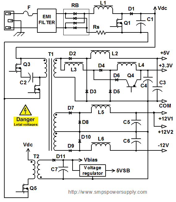
All electronic systems and equipment, regardless of their size or function, share a common requirement: a power supply unit (PSU) that converts input voltage into suitable voltage levels for their circuits. The most prevalent type of PSU today is...
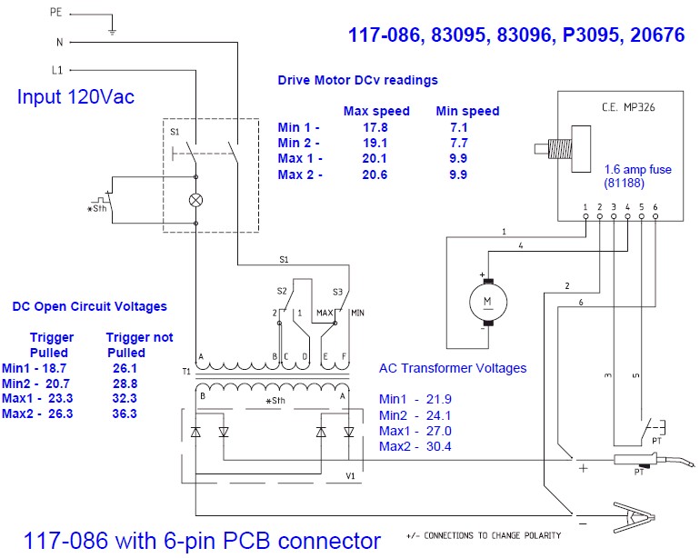
The wire speed DC motor consistently receives approximately 20 volts, irrespective of the switch position on the nozzle handle. The switch has been tested with an ohmmeter and functions properly. Even after disconnecting the switch from the circuit board,...
This circuit utilizes the widely available LM3914 integrated circuit (IC). The IC is straightforward to operate, does not require external voltage regulators due to its built-in voltage regulation feature, and can be powered from nearly any voltage source. The LM3914...
Features: 3-12 V, 1 A, over-current protection. This is a simple yet reliable device based on one of the oldest integrated voltage regulators, the LM723. R2 sets the output voltage. The maximum current is determined by the value of...
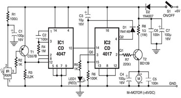
The following circuit illustrates an Infrared Toy Car Motor Controller Circuit Diagram. This circuit is based on the 4017 IC. Features: operating at .. The Infrared Toy Car Motor Controller Circuit utilizes a 4017 Decade Counter IC, which is integral...