
Feedback Band-Pass Filter

The described circuit functions as a graphic equalizer, utilizing a series of parallel band-pass filters that are each tuned to specific frequency bands, typically spaced by octaves. This configuration allows for individual adjustment of each band's amplitude through potentiometers located on the front panel, enabling users to tailor the overall frequency response of the audio signal.
The active band-pass filter design presents notable advantages. The absence of inductors simplifies the circuit, reducing both size and cost, particularly at lower frequencies where inductors can be bulky and expensive. The design also requires only a single operational amplifier (op-amp), which minimizes component count and complexity. However, one must consider the interdependence of the center frequency (fo) and the quality factor (Q) when making adjustments. Altering the resistance value of R2 will affect fo, but it will also inadvertently modify the Q, thus complicating the tuning process.
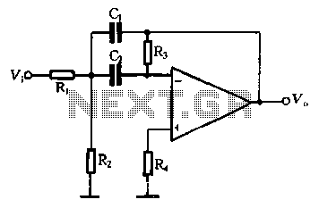
The circuit achieves its band-pass characteristics through its topology, where resistors and capacitors are arranged to form both high-pass and low-pass configurations. Specifically, R2 and C2 create a differentiator-like response, while C1 and R1A/B function as an integrator-like circuit. Setting C1 equal to C2 streamlines the design of the Multiple Feedback Band-pass filter, facilitating its implementation.
Component tolerances play a critical role in tuning accuracy. For example, if R2 deviates by 5% from its intended value, the center frequency fo will also shift proportionally, approximately by 2.4%. This sensitivity necessitates careful selection and calibration of components to maintain desired performance.
To determine the center frequency of the filter, two methods are available: observing the peak gain on a frequency response curve or identifying the frequency at which the phase shift crosses zero. The latter method is particularly useful for filters with low Q factors, where gain peaks may be less distinct. Monitoring phase shifts can be accomplished by incorporating phase trace measurements.
For precise tuning of the center frequency, a potentiometer can be integrated into the R2 position. However, this adjustment will also influence the bandwidth (BW), which may be less critical than ensuring the accuracy of the center frequency itself. Overall, this circuit design exemplifies a practical approach to audio signal processing, balancing ease of implementation with performance considerations.One application of this handy circuit is a graphic equalizer, created by feeding a signal to a number of parallel band-pass filters each tuned to a different frequency; typically octaves apart. Then, you can adjust the strength in each band via a front panel potentiometer. The outputs of all the filters are then summed to create overall frequency response of the equalizer.
There's a couple of advantages to this active band-pass filter. First, you don't need an inductor (bulky and expensive at low frequencies) to create the band-pass shape. And second, it only needs one op amp device. One disadvantage is the nature of adjusting the center frequency fo. Adjustments are not orthogonal (independent). You can tune fo with a resistor, but, the Q also changes. Still, the circuit is easy to implement and is useful for Q's up to about 20. But you've got to be aware how component tolerances alter your tuning frequency. And, you'll need an op amp with enough horsepower so it won't spoil your frequency response. You can visualize the band-pass nature of this circuit by inspecting its topology - R2 and C2 form a differentiator like circuit (high-pass), while C1 and R1A/B form an integrator like circuit (low-pass).
Letting C1 = C2 makes the Multiple Feedback Band-pass filter straight forward to design. Just follow these simple steps. As an example, suppose R2 value differs by 5 % of the design value. What is the effect on tuning? From the equations, fo is a function of the square root of R2. So you can expect the center frequency to change by ?5% or about 2.4 %. Increase R2 to 15.9 k x 1.05 = 16.7k and see what happens to fo. Use a cursor to get an accurate measure of fo. Where exactly is the center frequency of this filter? There's two ways to find the tuned frequency of a band-pass filter: 1. Find the peak of the gain versus frequency curve. 2. Find the frequency where the phase goes through zero. The latter may come in handy for low Q filters where the peak is less pronounced. To watch the phase shift change versus frequency, add the trace VP(4) where P indicates Phase. The phase looks pretty much like your typical LCR filter, positive phase (inductive) below fo, zero phase at fo, and negative phase (capacitive) above fo. If you need to precisely tune the center frequency, you could stick a potentiometer at R2. But as you can see from the upper right equation, the BW will also be effected. However, the exact bandwidth may not be as critical as the center frequency. 🔗 External reference
Related Circuits
This active subwoofer filter circuit is a 24 dB per octave filter with a Bessel characteristic and a cutoff frequency of 200 Hz. It is suitable for those experimenting with audio circuits in the subwoofer range, as all audio...
This application note discusses the design of a UHF ingress filter intended for a Satellite DBS tuner. The filter is designed to achieve 20 dB of stopband attenuation within the frequency range of 54-650 MHz, while maintaining an in-band...

This is a simple low pass filter that can be used at any audio circuitry. It uses the 741 opamp. More: Do not forget to use double power supply of 5 volts. You can use 2 batteries as shown...
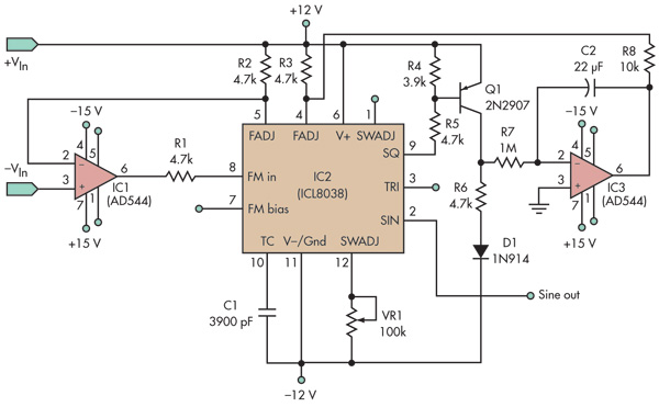
This basic voltage-controlled oscillator (VCO) and waveform generator integrated circuit (IC) circuit features a voltage follower loop (formed with IC1) and a symmetry feedback loop (IC3) designed to eliminate asymmetric duty cycles that can lead to distortion at low...

Band-pass filter used for a single channel, fH 50Hz, fL 13kHz. A band-pass filter (BPF) is an electronic circuit that allows signals within a specified frequency range to pass through while attenuating signals outside that range. In this case, the...
The performance of a second-order band-pass filter is primarily influenced by the quality factor (Q) and the center frequency (Si). To adjust the Q value, R3 should be modified first, followed by adjustments to C0. However, these adjustments will...