
Subwoofer Filter Circuit

The active subwoofer filter circuit is designed to effectively manage audio signals, particularly in home theater and professional audio applications. The circuit's architecture, featuring multiple op-amps, enables precise control over the audio frequency response, ensuring optimal performance for subwoofers and satellite speakers. Each op-amp stage is carefully selected to provide the desired filtering characteristics, with Bessel filters chosen for their phase response, which is critical in maintaining audio clarity and coherence in multi-speaker setups.
The symmetrical power supply requirement ensures stable operation across the circuit, minimizing noise and distortion. The choice of op-amps, including the LM833, TLMC662, and LME49726, reflects a balance between performance and operational voltage, allowing flexibility in various applications. The ability to adjust component values for both high-pass and low-pass sections provides users with the tools necessary to fine-tune the filter's response to suit specific acoustic environments or personal preferences.
In practical implementation, the circuit can be integrated into existing audio systems with minimal modification, making it a versatile solution for enhancing low-frequency audio reproduction. The detailed pin configuration and operational guidelines ensure ease of use for engineers and hobbyists alike, facilitating straightforward assembly and troubleshooting. Overall, this active filter circuit exemplifies a sophisticated approach to audio signal processing, catering to the nuanced demands of modern audio systems.This subwoofer active filter circuit is a 24 dB octave filter with a Bessel character and cutoff frequency of 200 Hz. So, if you are interested in experimenting with audio circuits in subwoofer range, this circuit is for you.
In subwoofer range, all audio frequencies below 200 Hz can be fed to a single speaker box since the human directional perce ption of sound diminishes at this frequency range. The normal stereo signals above 200 Hz can be fed to 2 satellite speakers. How does the subwoofer filter works: A1 and A2 buffer the signals coming from right and left channels. Opamp combinations A2/A4 and A9/A10 function as the highpass filters. The outputs are then connected to the final amplifiers of the battelite boxes. Signals from both channels are fed to A5. Opamps A6/A7 function as the lowpassfilter, A8 as the output amplifier for the subwoofer signal. The signal level can be balanced between the subwoofer and the satellite lines. The power needed for this filter circuit must ne a symmetrical power supply. The opamps can have either JFET or bipolar inputs. super circit. I use this circuits in DTS cinema surround system in many theatres. Also i use it in my 5. 2 ch DOLBY DIGITAL 3D hOLOPHONIC SURROUND SYSTEM . Pin 1 is OP 1 output. Pin 2 is OP 1 inverting input. Pin 3 is OP 1 non-inverting input. Pin 4 is VEE (most negative supply ground can be used, but the virtual ground must be generated using two resistors and an electrolytic capacitor).
Pin 5 is OP 2 non-inverting input. Pin 6 is OP 2 inverting input. Pin 7 is OP 2 output. Pin 8 is VCC (most positive supply). The LM833 is capable of 30VDC operation. The TLMC662 is capable of 12VDC operation, but has CMOS inputs and can swing closer to its rails. The LME49726 operates on 5V, buhas such low distortion commercial distortion analyzers have trouble reading it (VOUT = 3. 5VP-P, VDD = 5. 0V, THD = 0. 00008%). The upper and lower sections are high pass circuits and they are set for about 200Hz. Changing the capacitors (C2, 3, 4, 5, 13, 14, 15, 16) is the easiest way to adjust the frequncy for those.
Just make sure all capacitor values are the same. Double the value and you will halve the frequency. Cut the value in half and you will double the pass band. For the middle section, a low pass filter, adjusting the resistors (R9, 10, 11, 12) changes the frequency. The same rule applies. Keep all resistance values the same and increase to lower the pass band frequency and reduce the resistance to raise the frequency.
The web page has a great calculator for these filters. Thanks for the link. I still don`t understand the different values of resistors on each stage of the high pass filter and the different values of cap on each stage of the low pass. An active filter like this is just an RC filter with a way of feeding back some of the signal in a way that the impedence of the previous components can`t affect.
This can help make the RC filter sections (you can see both kinds of stages are made with 2 resistors and 2 capacitors) more effective and the roloff at the chosen frequency sharper. This is where the filters Q comes into it. This is basically a measure of how sharp the filters roloff is. For each kind of filter, either the resistive or capacitive elements have a larger effect on the Q of the filter (yes, the Q stands for quality).
For high pass filters, the different resistor values allow one to adjust the Q as well as setting the frequency. For low pass filters, the capacitors do this. Thus, each section either uses all the same resistor values or all the same capacitor values. A simple RC filter has a 6db per octave value calculated from f6db=1/2*pi*R*C (with R in ohms and C in farads and f in Hertz).
To get better than 6db per octave, you would use an active filter and be able to adjust the Q for 15db per octave. As I tried to explain, these are not simple RC filters with 6db per octave rolloff. By using a buffe 🔗 External reference
Related Circuits
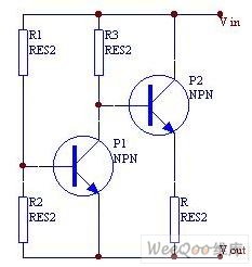
When the current is below the specified threshold, the bias current supplied by resistor R1 causes transistor P3 to saturate and conduct. In this state, it is unable to regulate the current effectively. Conversely, when the current reaches or...
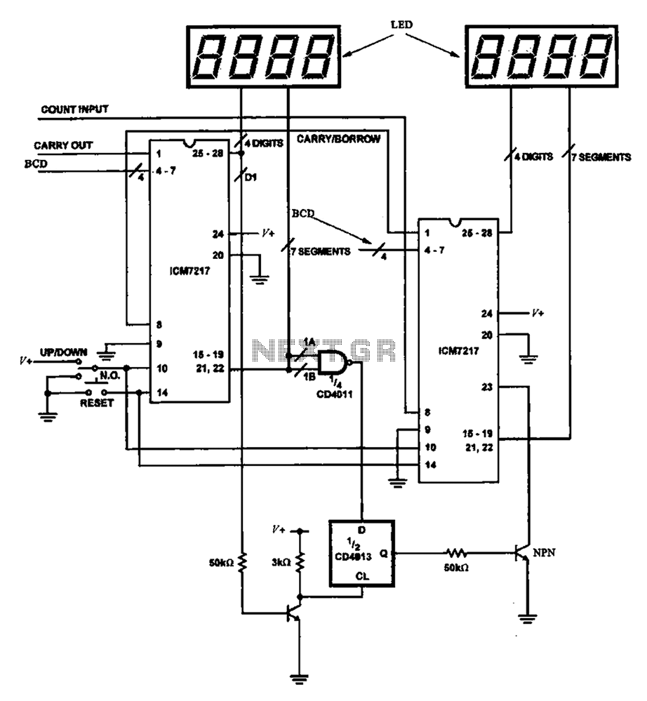
Figure 8 illustrates a potential digital counter circuit. This circuit employs two ICM7217 integrated circuits, with each controlling four digital display tubes. The digital counter circuit primarily utilizes the ICM7217, a highly integrated chip designed for driving seven-segment displays. Each...
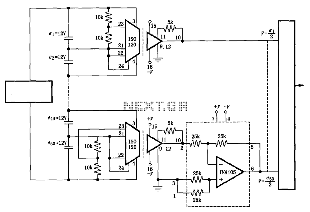
The circuit utilizes the ISO120 and INA105 instrumentation amplifiers to create a battery monitoring system for a 600V battery setup composed of 50 series-connected 12V batteries. This circuit is designed to detect charging and discharging conditions to prevent overcharging...
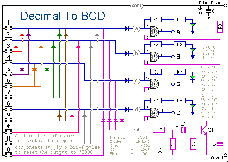
When a keypad switch is pressed, this circuit reproduces its value in Binary Coded Decimal (BCD) format. A 12-keypad is used, but it can be expanded to 16 keys for Hexadecimal to BCD conversion. The circuit consists of two...
The circuit diagram presented is for an IC controlled emergency light with a charger, functioning as a 12V to 220V AC inverter circuit. Key features include automatic activation of the light during a mains failure and a battery charger...
One of the most effective communication methods to be implemented in a digital system is the use of the RS232 serial line. The microcontroller 89S51 is equipped with a UART, allowing it to perform serial communication at RS232 levels...