
Feld-Hell electronic circuitry and schematics

The circuit described operates primarily as a communication device utilizing a 900 Hz tone generated by an LC oscillator. The dual-function transformer SG plays a critical role in both generating the tone and coupling to the output stages. The bi-directional "Leitung" port allows for seamless communication, ensuring that the device can both send and receive keyed tones effectively. The design accommodates varying line impedances, ensuring compatibility with standard telephone systems while maintaining signal integrity. The inclusion of a bandpass filter enhances audio quality, allowing for clear tone transmission and reception. The use of shielding and ground connections minimizes interference, further enhancing the reliability of the device in various operational environments. The ability to receive tones from a radio receiver adds versatility to the system, expanding its functionality in communication applications. Overall, the schematic represents a sophisticated integration of components designed to facilitate effective and reliable communication through tone generation and reception.The 900 Hz tone is generated with an LC-oscillator. The "L" part of the "LC" is provided by the inductance of the oscillator`s output coupling transformer T1. It is a variation on one of the two standard Hartley oscillator configurations (named after its inventor Ralph Hartley, who was awarded the patent in 1920).
It has two series-connected (and coupled) inductors and a single capacitor (here: C18). The two inductors are formed by the tapped windings on one side of coupling/isolation transformer SG ("Summer-G bertrager"). So this transformer cleverly fulfills two functions. When a key is selected via the keyboard, the continuous 900 Hz tone is keyed by the associated track of the character drum ("Geberwalze").
See the " raster can " section of the "how it works" page. The tone can also be keyed with the "Morse" telegraphy key of the keyboard. The keyed tone is output via transformer T2 to the telephone line I/O port ("Leitung" connectors La and Lb/E), and the telephone jack that is connected in parallel to this port. The "Leitung" port has an impedance of 800 ohm (at 900 Hz). This may at first appear to be incompatible with what many people consider to be the (fixed) impedance of standard POTS telephone land-lines: 600 ohm.
However, keep in mind that phone lines only have 600 ohm impedance at one single frequency: about 1300-1400 Hz. For 900 Hz (the Hellschreiber tone), the impedance of a standard phone line is actually 800 ohm! At the high end of the phone-voice bandwidth (3400 Hz) the line impedance drops to about 350 ohm. See ref. 1. The impedance of the connected line is not at all critical, as long as the end-to-end attenuation of the 900 Hz tone is less than 46 dB (5.
3 Neper). The "Leitung" port is bi-directional: keyed tones are output to the phone line, and tones from an other Hellschreiber are received from this phone line. The latter are, therefore, also transformer coupled. The output level of the keyed 900 Hz tone is at least 2. 2 V at the La-Lb/E port, and at least 6. 1 V at the "EmpfG¤nger" port (ref. 13). The same transformer T2 provides coupling of the keyed tones to the bandpass filter / pre-amplifier stage.
This causes the text that is transmitted by a Feld-Hellschreiber, to be printed locally, as it is transmitted. This creates a record of the transmitted text. Note that this allows full-duplex communication (except when using the character drum to directly key an CW transmitter)!
Obviously, simultaneously sent and received text are printed on top of each other. This was actually used during the standard speed adjustment procedure upon establishing a communications link (ref. 54). Most Feldfernschreibers are equipped with a 12-pin round connector on the front panel. If the corresponding plug is inserted, the keying contacts of the character drum are diverted to this connector, and the keyed tone is no longer coupled to the pre-amplifier stage or the line output.
All transformers have a static shield that is connected to ground. Additionally, T1 is placed in a shielding box that is also connected to chassis ground. Shielded wiring is used where it is prone to picking up noise or hum. Tones can also be received from an other Hellschreiber via a radio receiver. The associated "EmpfG¤nger" (receiver) input port passes through a line filter (not shown in the schematic above), and is tied across the secondary side of transformer T2. This is sort of a "transformer-coupled wired-OR". This port has an impedance of 4000 © (at 900 Hz). At this point, a potentiometer provides audio input volume control. The potmeter output is passed through an LC "Tonsieb". I. e. , a bandpass filter. As for the tone oscillator, the "L" part of the "LC" is formed by a transformer. In this case, the T3 coupling to the pre-amplifier tube. The filter is turned off by manually switching-in a "spoiler" resistor between the audio gain potentiometer and the filter.
Per ref. 2, th 🔗 External reference
Related Circuits
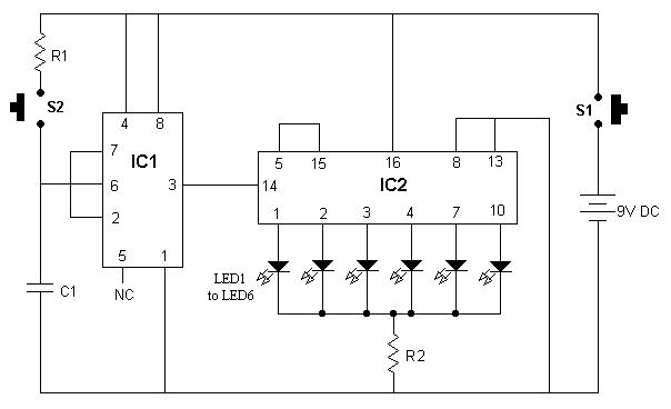
It is advisable to enclose this circuit in a box and label each LED with numbers from 1 to 6. When switch S1 is momentarily pressed, one of the six LEDs will illuminate, with the number corresponding to the...
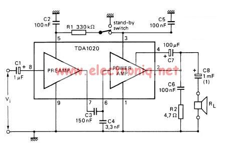
The TDA1020 is a monolithic integrated 12 W audio amplifier housed in a 9-lead single in-line (SIL) plastic package. Although it is designed primarily for car audio applications, it can also be utilized in various other audio applications. The TDA1020...
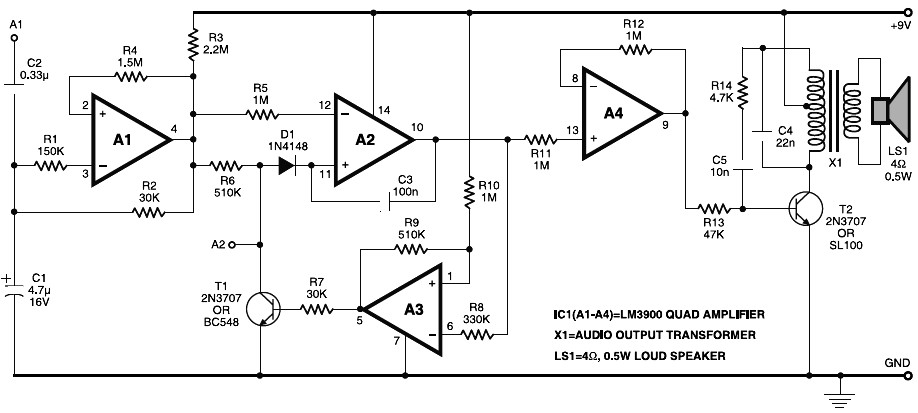
Electronic horn circuit diagram. When the power line is switched on, a basic tone is produced by transistor T2 and transformer X1, which is frequency-modulated by a wandering voltage generator affected by a low-frequency square wave generator. This is...
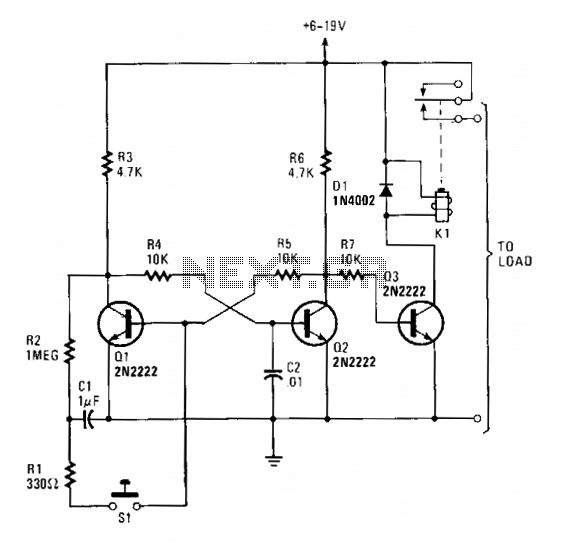
Transistors Q1 and Q2 form a flip-flop configuration, while Q3 operates a reed relay. Upon initial power application to the circuit, Q1 and Q3 are in a conducting state, whereas Q2 remains off. A momentary closure of switch S1...
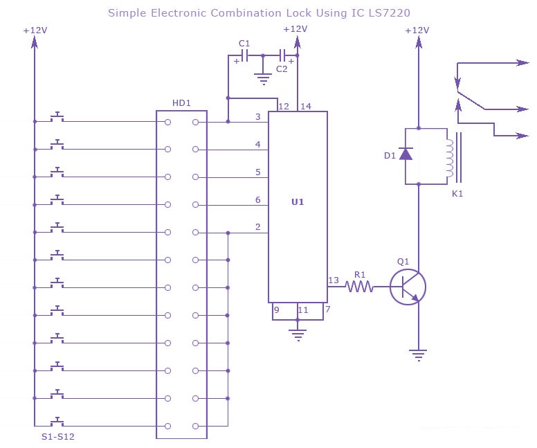
A simple electronic combination lock using the IC LS7220. This circuit employs a relay to control any device when a combination of four digits is entered. Keypads serve as the input method for entering the digits, and the correct...
The circuit is designed to operate with an external power supply, which is why it does not include a transformer, rectifier, or filter capacitors in the schematic. However, these components can be added if desired. To utilize the circuit,...