
Fet Led schematic

The circuit described utilizes a Field Effect Transistor (FET), specifically the BF256C, to control the current flowing through an LED. The FET operates by using voltage applied to its gate terminal to modulate the current between the source and drain terminals. This allows for efficient control of the LED brightness based on the input voltage, which can range from 4V to 30V.
In this configuration, the LED is connected in series with a current-limiting resistor to ensure that the current remains constant at approximately 15mA, which is optimal for typical LEDs to prevent damage while providing adequate brightness. The resistor value can be calculated using Ohm's law, factoring in the forward voltage drop of the LED, which is typically around 2V for standard red LEDs. For example, if the supply voltage is 9V, the resistor value can be calculated as follows:
R = (Vsupply - VLED) / ILED = (9V - 2V) / 0.015A = 466.67 ohms.
A standard resistor value of 470 ohms can be used in this case.
The circuit also allows for AC power supply operation, which may cause the LED to dim slightly due to the nature of the alternating current. The diode (D1 = 1N4148) serves as a rectifier, allowing only the positive half-cycles of the AC signal to pass through, thus converting the AC supply into a pulsating DC supply. This characteristic may result in a noticeable reduction in brightness compared to a purely DC operation.
Overall, this circuit provides a simple and effective means of controlling LED brightness using a FET while allowing for flexibility in power supply options. Proper consideration of component ratings and characteristics is essential for optimal performance and reliability.This circuit uses the effect of a FET as the power to act through the gate with the source to connect. The voltage may vary between 4V and 30V, the current through the LED should constantly be around 15mA.
The circuit can also be powered by AC, the LED will dim slightly. T1 = BF256c D1 = 1N4148 Simple LED = LED 🔗 External reference
Related Circuits

When discussing fan control, there are generally two methods: linear control and pulse-width modulation (PWM) control. Linear control is the most commonly used method, which involves reducing the voltage supplied to the fan. For a fan rated at 12...
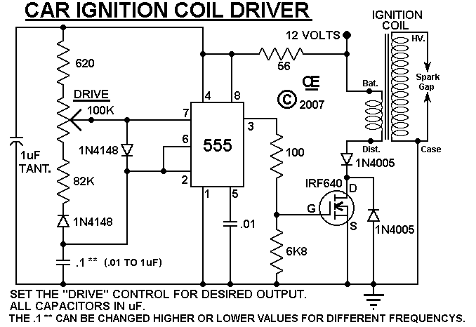
An ignition coil is being used to generate sparks, controlled by a MOSFET powered by a 555 timer. The MOSFET is confirmed to be switching. The circuit involves a 555 timer configured in astable mode to generate a pulse-width modulation...
The schematic below illustrates a simple LED flasher circuit. This circuit utilizes three LEDs that begin to blink or flash upon receiving a 9-volt supply. It is straightforward in design, employing a self-flashing LED (LED 1) to trigger the...

The circuit for the localizer is based on a quad-band GSM/GPRS module interfaced with a microcontroller. After initializing the I/Os and UARTs, the microcontroller enters a loop waiting for events, such as the arrival of an SMS or the...
A student is working on a project related to active electronics as part of their second year in a bachelor's program in audio production. Active electronics refers to electronic circuits that require an external power source to operate, typically involving...
This audio mixer circuit does not utilize a low impedance input to mix non-ideal sources; instead, it employs multiple amplifiers to provide ideal sources prior to mixing through simple resistors. An ideal source is characterized by low impedances, which...