
simplest led flasher

The described LED flasher circuit is a basic yet effective design that illustrates the principles of LED operation and flashing mechanisms. The circuit is powered by a 9-volt battery, which is connected to the anode of the self-flashing LED (LED 1). This LED is designed with an internal oscillator that controls its flashing frequency. As LED 1 flashes, it generates a pulsing signal that is also applied to the other two general-purpose LEDs (LED 2 and LED 3).
The self-flashing LED typically incorporates a small integrated circuit (IC) that modulates the current flowing through it, causing it to turn on and off at a predetermined rate. This built-in circuitry simplifies the design, as it eliminates the need for external components such as resistors or capacitors that are commonly used in other flashing LED circuits.
LED 2 and LED 3 are connected in parallel with LED 1, allowing them to share the same voltage and current. The choice of colors for these LEDs can vary based on user preference, and their arrangement can create visually appealing light patterns. The circuit's simplicity makes it ideal for educational purposes, providing a clear demonstration of how LEDs function and how they can be used in various applications, such as decorative lighting or indicators.
To ensure optimal performance, it is crucial to select self-flashing LEDs that meet the voltage and current requirements of the circuit. Operating outside the specified voltage range may lead to suboptimal performance or damage to the LEDs. Therefore, confirming specifications with the manufacturer is essential for ensuring reliability and longevity in operation.Here`s The schematic shown below is a simplest LED flasher circuit. The circuit is using three LEDs which will start blinking or flashing when we provide 9 volt to the circuit. The circuit is so simple it uses a self flashing LED (LED 1) to make all LEDs flash. Self flashing LEDs have a built in circuit to make them flash and they are also very ch eap now a days. Most self blinking LEDs operate from 3. 5V to 9V but it is better to confirm from the seller or manufacturer to be sure. LED 2 and LED 3 are general LEDs of any colour. 🔗 External reference
Related Circuits

The LT1618 not only provides an accurate input current limit but also functions as a regulated output current source suitable for current-source applications. One such application is driving white LEDs, for which the LT1618 is particularly well-suited. It operates...
The circuit utilizes two quad voltage comparators (LM339) to illuminate a series of eight LEDs that indicate volume levels. Each of the eight comparators is biased at progressively higher voltages established by a voltage divider, allowing the lower right...

Each step will result in a self-functional unit. By the end of this process, it will be possible to link the steps together into a powerful FM transmitter. This section will explain the main controlling unit for the FM...
This article was previously published, but the intention is to spread the idea further, potentially inspiring new concepts. An improved version was being developed using an ULN2803A instead of multiple BC547B transistors and optional Zener diodes to ensure that...

This application note discusses the use of SEPIC power modules to supply the necessary power for driving high-brightness LED arrays. These arrays serve as display backlights and necessitate a wide dimming range. The SEPIC configuration offers an efficient and...
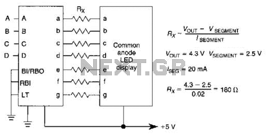
An IC1, such as the 7447, drives a common anode 7-segment LED display. The current-limiting resistor R must restrict the segment current to the rated value at the maximum supply voltage. A sample calculation is provided. The 7447 integrated circuit...