
FET VOLTMETER
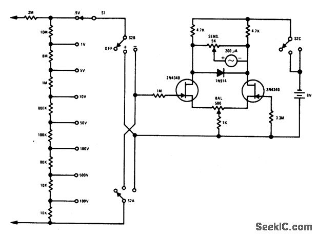
The FETVM (Field Effect Transistor Voltmeter) incorporates advanced semiconductor technology to enhance measurement accuracy and stability. The removal of the line cord simplifies the design and improves portability, making it suitable for various applications in electronics testing and troubleshooting. The use of the 2N4340 transistor, known for its minimal leakage current and low noise characteristics, contributes to the overall performance of the device.
The circuit typically includes a high-impedance input stage that utilizes the 2N4340 to amplify the input voltage without introducing significant noise or distortion. The output stage may employ additional amplification or signal conditioning circuits to ensure that the measured voltage can be accurately displayed or recorded.
Drift rates in the FETVM are significantly lower than those found in traditional vacuum tube voltmeters, allowing for more reliable long-term measurements. This feature is particularly beneficial for applications that require precise voltage readings over extended periods. The design may also incorporate temperature compensation techniques to further enhance stability and accuracy.
Overall, the FETVM represents a significant advancement in voltmeter technology, offering improved performance and convenience over its vacuum tube predecessors. It is well-suited for use in laboratories, fieldwork, and any application where accurate voltage measurement is critical.This FETVM replaces the function of the VTVM while at the same time ridding the in-strument of the usual line cord. In addition, drift rates are far superior to vacuum tube circuits allowing a 0. 5 volt full scale range which is impractical with most vacuum tubes. The low-leakage, low-noise 2N4340 is an ideal device for this application. 🔗 External reference
Related Circuits
The circuit requires a threshold of 2 volts, which allows only a minimal current to flow through the transistor. It is necessary to determine the voltage required to fully turn on the transistor. Additionally, it is important to establish...
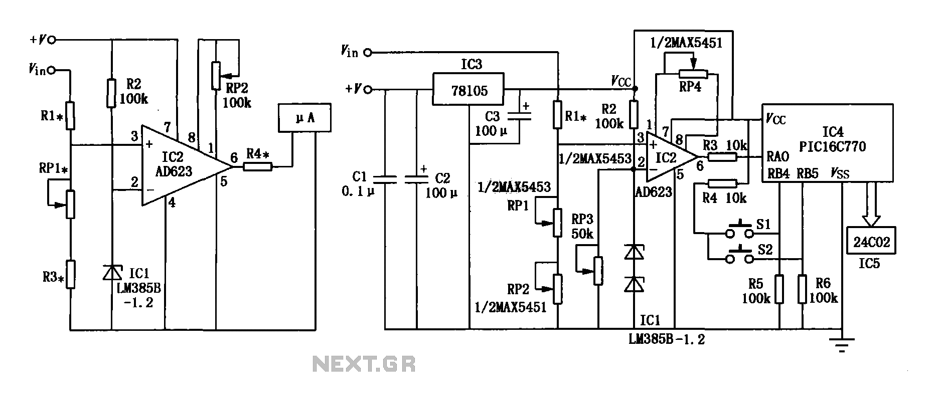
The range precision voltmeter electrical schematic is depicted in Figure (a) below. It features an amplifier circuit and several high-precision components that significantly enhance the performance range of the voltmeter. The inverting input of the instrumentation amplifier AD623 (IC2)...
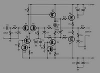
The supply voltage rails were conservatively maintained at +40V and -40V. For those interested in experimentation, the supply voltage can be increased to a maximum of +50V and -50V, enabling the amplifier to reach its target output of 100W...

This is a circuit design for a digital voltmeter with an LED display. It is suitable for measuring the output voltage of a DC power supply. The circuit features a 3.5-digit LED display with a negative voltage indicator and...
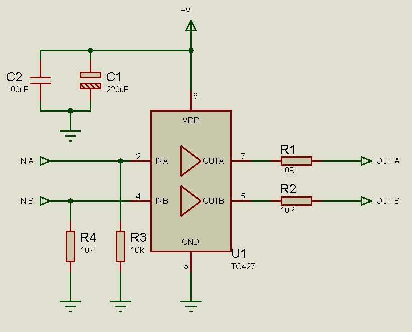
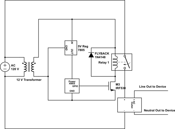
MOSFETs cannot simply be connected to the drive signal and expected to function correctly. Due to their construction, driving MOSFETs can be complex, particularly for beginners. Many users frequently seek assistance with MOSFET drive issues on various blogs, websites,...
The TLE6282G is an H-Bridge and Half Bridge Driver IC designed for high-current DC brush motor applications in PWM control mode. It is suitable for use in injector and valve applications across 12V, 24V, and 42V power networks. This...